Vertical transistors and output prediction logic circuits containing same

Inactive Publication Date: 2005-05-31
MICRON TECH INC
View PDF13 Cites 110 Cited by
  • Summary
  • Abstract
  • Description
  • Claims
  • Application Information

AI Technical Summary

Benefits of technology

[0011]According to another embodiment of the present invention, ultra-thin body vertical NMOS transistors are fabricated by epitaxially growing a relaxed silicon germanium (SiGe) body region by ultra-high vacuum chemical vapor deposition (UHVCVD) and subsequently forming a strained silicon channel in contact with the relaxed silicon germanium (SiGe) body region.
[0012]According to yet another embodiment of the invention, CMOS gate arrays with ultra-thin vertical NMOS transistors with relaxed silicon germanium (SiGe) body regions and strained silicon channels are employed to form a pseudo-NMOS OPL circuit. The pseudo-NMOS logic circuit includes a number of logic inputs, a clock input and an output. The number of logic inputs are coupled to a number of gates of the vertical ultra-thin NMOS transistors having relaxed silicon germanium (SiGe) body regions and strained silicon channels. The clock input is coupled to a gate of a vertical ultra-t

Problems solved by technology

Another drawback is that the hole mobility in a PMOS transistor is about three times lower than the electron mobility in an NMOS transistor of comparable size.
Nevertheless, the increase in the size of the PMOS transistors increases the stray capacitive loads, which in turn requires an even larger area for the circuits and a very inefficient area utilization.
Although advances in the integration of CMOS logic families are becoming increasingly notable, a major disadvantage remains the slow speed of the integrated CMOS logic circuits.
Thus, the use of PMOS devices for logical switching transitions generally results in a slower speed for the integrated CMOS logic circuit.
In addition to the d

Method used


Image

  • Vertical transistors and output prediction logic circuits containing same
  • Vertical transistors and output prediction logic circuits containing same
  • Vertical transistors and output prediction logic circuits containing same

Examples


Example

[0029]In the following detailed description, reference is made to various specific embodiments in which the invention may be practiced. These embodiments are described with sufficient detail to enable those skilled in the art to practice the invention, and it is to be understood that other embodiments may be employed, and that structural, logical, and electrical changes may be made.

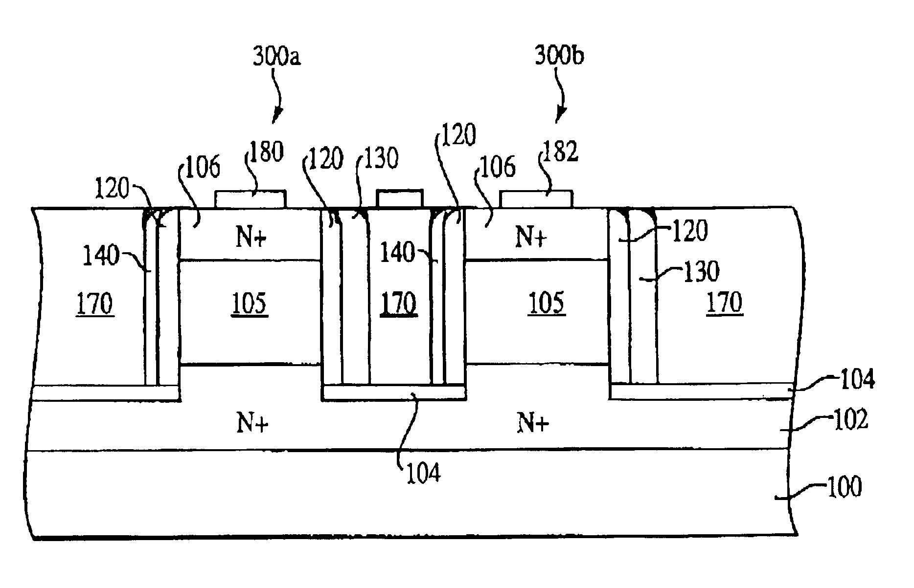
[0030]The term “substrate” used in the following description may include any semiconductor-based structure that has a silicon surface. Structure must be understood to include silicon, silicon-on insulator (SOI), silicon-on sapphire (SOS), doped and undoped semiconductors, epitaxial layers of silicon supported by a base semiconductor foundation, and other semiconductor structures. The semiconductor also need not be silicon-based. The semiconductor could be silicon-germanium, germanium, or gallium arsenide. When reference is made to a substrate in the following description, previous process steps may have b...


PUM


Abstract

Very fast integrated OPL circuits, such as pseudo-NMOS OPL and dynamic OPL, comprising CMOS gate arrays having ultra-thin vertical NMOS transistors are disclosed. The ultra-thin vertical NMOS transistors of the CMOS gate arrays are formed with relaxed silicon germanium (SiGe) body regions with graded germanium content and strained silicon channels.

Description

FIELD OF THE INVENTION[0001]The present invention relates generally to the field of integrated circuits, and more specifically, to novel output prediction logic circuits and methods of formation.BACKGROUND OF THE INVENTION[0002]Complementary Metal Oxide Semiconductor (CMOS) technology is well-known in the fabrication of integrated circuits. CMOS technology is employed not only for analog integrated circuits, but also for digital integrated circuits to which they confer low power dissipation, high density of integration and low cost of fabrication.[0003]FIG. 1 illustrates a prior art conventional static CMOS NAND gate circuit 10. One of the drawbacks associated with the static CMOS NAND gate circuit 10 of FIG. 1 is that each input 12, 14 must drive two gates, the gate of an NMOS transistor and the gate of a PMOS transistor. Input 12 drives gates 16 and 18, while input 14 drives gates 20 and 22. As a result, large CMOS circuitry area and large number of metal wiring levels must be uti...

Claims


Application Information

Patent Timeline
IPC IPC(8): H01L29/76H01L21/336H01L21/02H01L29/66H01L31/115H01L31/117H01L21/8238H01L27/092H01L27/118
CPCH01L21/823885H01L27/11807H01L27/092H01L29/1054H01L29/161H01L29/165H01L29/66666H01L29/7827
Inventor FORBES, LEONARDAHN, KIE Y.
Owner MICRON TECH INC
Why Eureka
Try Eureka