

Image-sensing apparatus for selecting optical blur correction or electronic blur correction
a technology of optical blur correction and image sensor, which is applied in the field of image sensor, can solve the problems of deteriorating image quality, high power consumption of these components, and the optical correction scheme takes a long time to activate the blur sensor, so as to achieve the effect of correcting the blur of an image and low power consumption
- Summary
- Abstract
- Description
- Claims
- Application Information
AI Technical Summary
Benefits of technology
Problems solved by technology
Method used
Image

Examples
first embodiment
(1) First Embodiment
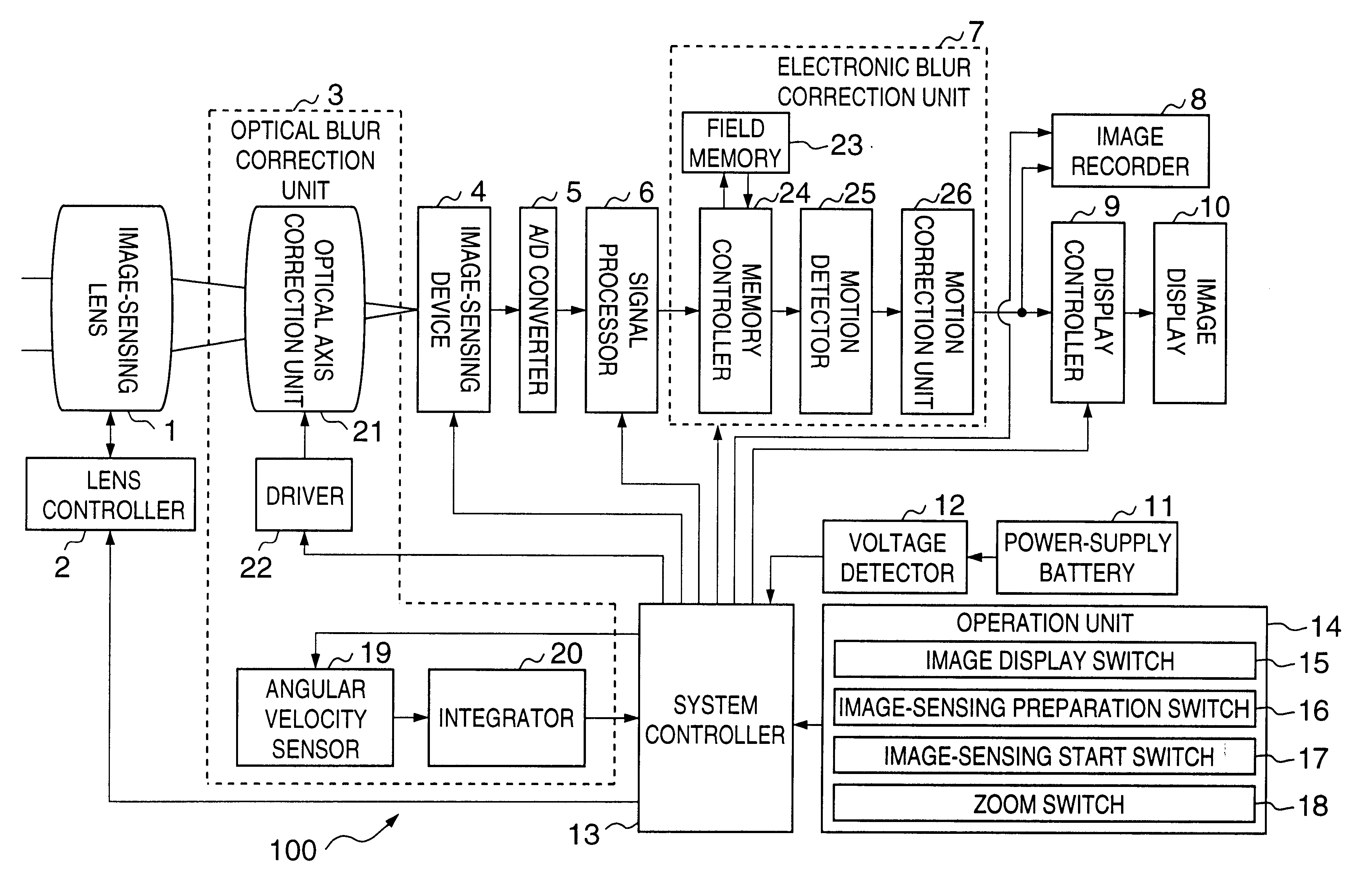
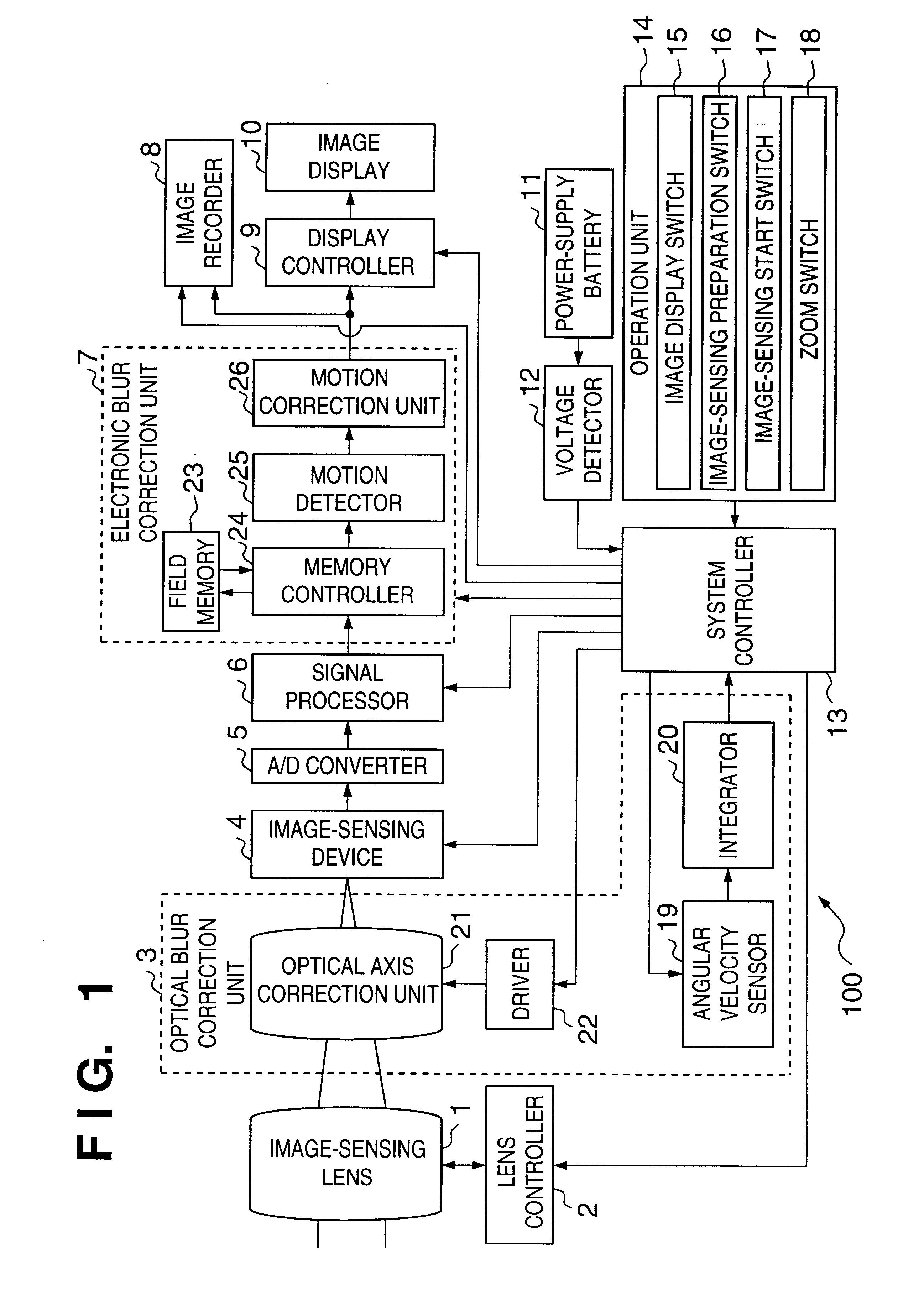
[0028]FIG. 1 is a block diagram showing the arrangement of a digital camera having a blur correcting function according to the first embodiment of the present invention. Reference numeral 1 denotes an image-sensing lens which optically forms an object image and has a zoom function. This image-sensing lens 1 includes a focusing lens and zooming lens. A lens controller 2 includes motors and gears for moving the focusing lens and zooming lens of the image-sensing lens 1 for focus adjustment and zooming, respectively, and an encoder for detecting the position of the focusing lens and / or the position of the zooming lens. An optical blur correction unit 3 corrects a blur of an object image by shifting the optical axis of the image-sensing lens 1. Details of this optical blur correction unit 3 will be described later.
[0029]Reference numeral 4 denotes an image-sensing device such as a CCD for receiving an object image formed on a light-receiving surface by the image-sens...
second embodiment
(2) Second Embodiment
[0049]The second embodiment differs from the first embodiment in that when electronic blur correction is performed in the image-sensing preparation stages, image synthesis is performed instead of shifting an image-sensing lens.
[0050]The arrangement of a camera according to the second embodiment is the same as the camera 100 described above, so a detailed description thereof will be omitted.
[0051]Electronic blur correction of this embodiment will be described in detail below with reference to FIGS. 6A and 6B. When an object is sensed by an image-sensing lens 1, the sensed image (a3) is temporarily saved in a field memory 23. After that, this image is read out, a motion detector 25 calculates a moving amount from the correlation between the readout image and an image of the next frame, and a motion correction unit 26 in an electronic blur correction unit 17 corrects an image blur. The obtained image (b3) is an image formed by omitting a peripheral portion (c) and ...
third embodiment
(3) Third Embodiment
[0053]The third embodiment differs from the second embodiment in the method of image synthesis.
[0054]The arrangement of a camera according to the third embodiment is the same as the camera 100 described earlier, so a detailed description thereof will be omitted.
[0055]Electronic blur correction of this embodiment will be described in detail below with reference to FIGS. 7A and 7B. When an object is sensed by an image-sensing lens 1, the sensed image (a4) is temporarily saved in a field memory 23. After that, this image is read out, a motion detector 25 calculates a moving amount from the correlation between the readout image and an image of the next frame, and a motion correction unit 26 corrects an image blur. The obtained image (b4) is an image formed by omitting a peripheral portion and extracting only a central portion from the initial image (a4). In this embodiment, however, the motion correction unit 26 reduces the image (a4) before blur correction and synth...
PUM
 Abstract
Description
Claims
Application Information