Developing apparatus and image forming apparatus using progressive wave electric field transport

a technology of progressive wave electric field transport and development apparatus, applied in the direction of electrographic process apparatus, instruments, optics, etc., can solve the problems of destabilization of the transport of the developer, inability to maintain the stable state of development for a long time, and the developer's transport is destabilized, so as to suppress the variation of the surface potential, the effect of stable development state and suppressing the variation of the developing potential

Inactive Publication Date: 2005-05-31
SHARP KK
View PDF21 Cites 22 Cited by
  • Summary
  • Abstract
  • Description
  • Claims
  • Application Information

AI Technical Summary

Benefits of technology

[0020]The present invention was made to solve the problems above. An object of the present invention is to provide a developing apparatus capable of (i) suppressing a variation of a surface potential of an insulating layer of transportation means at a time of transportation of developer, so as to prevent firm adhering of the developer to a surface of the transportation means, thereby transporting the developer to a development position always stably, and (ii) suppressing a variation of a developing potential between an image supporting body and the transportation means in a developing step, so as to attain an always stable state of development.

Problems solved by technology

However, with the conventional progressive wave electric field method, the developing apparatus has the following problems.
As a result, transportation of the developer is destabilized, for example, because the developer firmly adheres onto a surface of the transportation means.
As a result, a stable state of development cannot be maintained.
Specifically, if the pitch between adjacent ones of the electrodes is wide, a long time (transport time) is required for the developer to move between adjacent ones of the electrodes, although field intensity is high.
Therefore, unless an appropriate developer transportation condition is selected, it is impossible to transport the developer efficiently on the developer transportation means by using the progressive wave electric field.
Moreover, under the following conditions, developing apparatuses using a progressive wave electric field is susceptible to spatial and temporal distribution of a potential generated by the voltages applied to the electrodes: (i) a progressive wave electric field is generated on the surface (developer transportation surface) of the developer transportation member, that is, different voltages are applied to the electrodes, and (ii) a supporting surface (front surface) of the image supporting body, such as a photosensitive body, is right above or in close proximity with the surface of the developer transportation member after the image supporting body has moved in a perimeter direction.
This causes collisions of the developer with the developer itself, and increases a transportation speed of the developer.
Therefore, if the supporting surface of the image supporting body is completely soaked into the developer that is in the cloud-like state, so-called blotching is caused.
Incidentally, in a method using a progressive wave electric field, distribution of toner in the transportation path is uneven in a traveling direction.
Therefore, periodical density unevenness of the toner is caused.
However, in the foregoing conventional developing apparatus, despite the fact that (i) a traveling direction of the developer is a rotation movement direction of the image supporting body, and (ii) the toner having the uneven density on the transportation path faces the electrostatic latent image on the image supporting body and moves in parallel with the electrostatic latent image, no measure has been taken to suppress an influence of the density unevenness of the toner.

Method used


Image

  • Developing apparatus and image forming apparatus using progressive wave electric field transport
  • Developing apparatus and image forming apparatus using progressive wave electric field transport
  • Developing apparatus and image forming apparatus using progressive wave electric field transport

Examples


Embodiment Construction

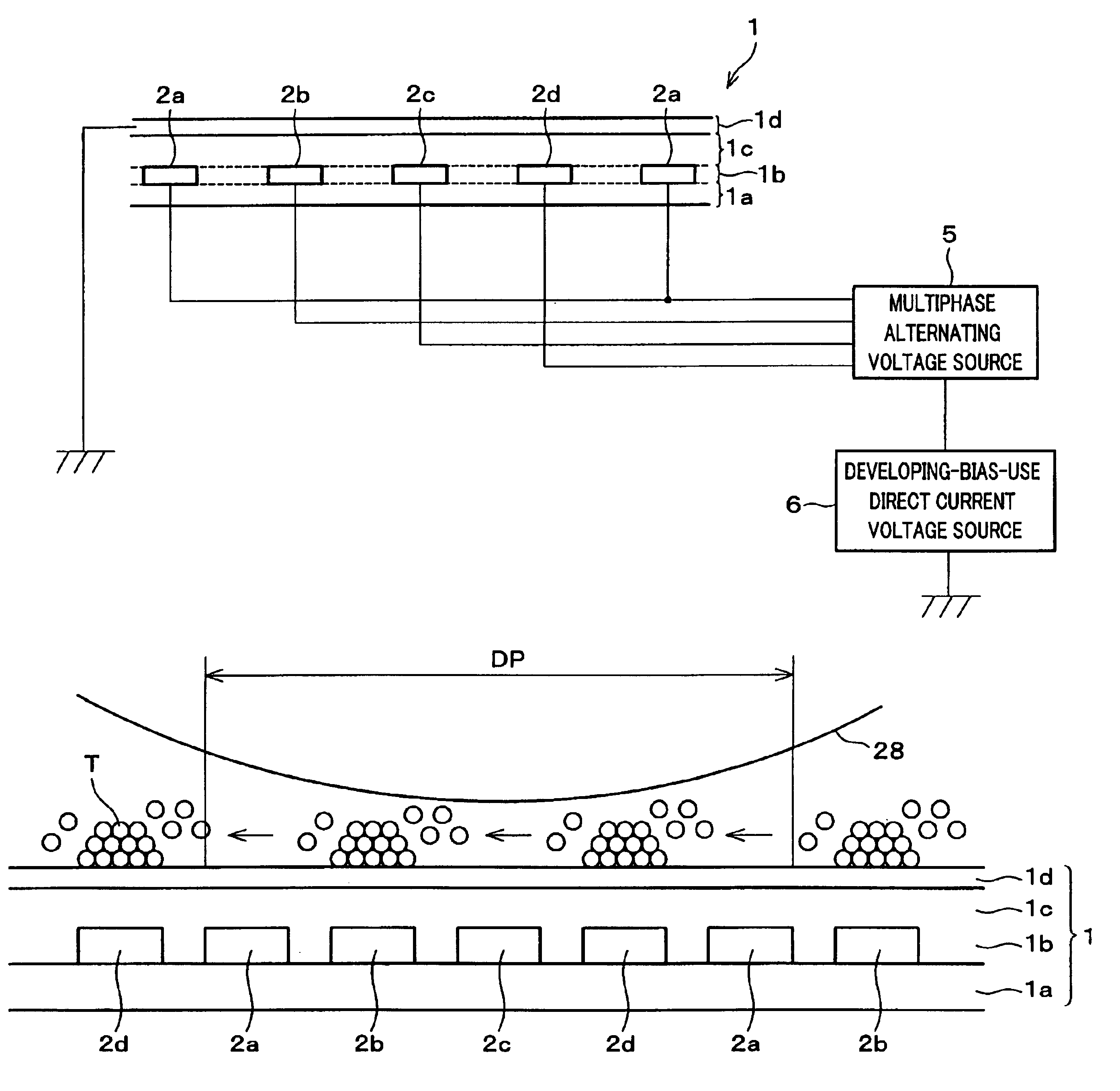
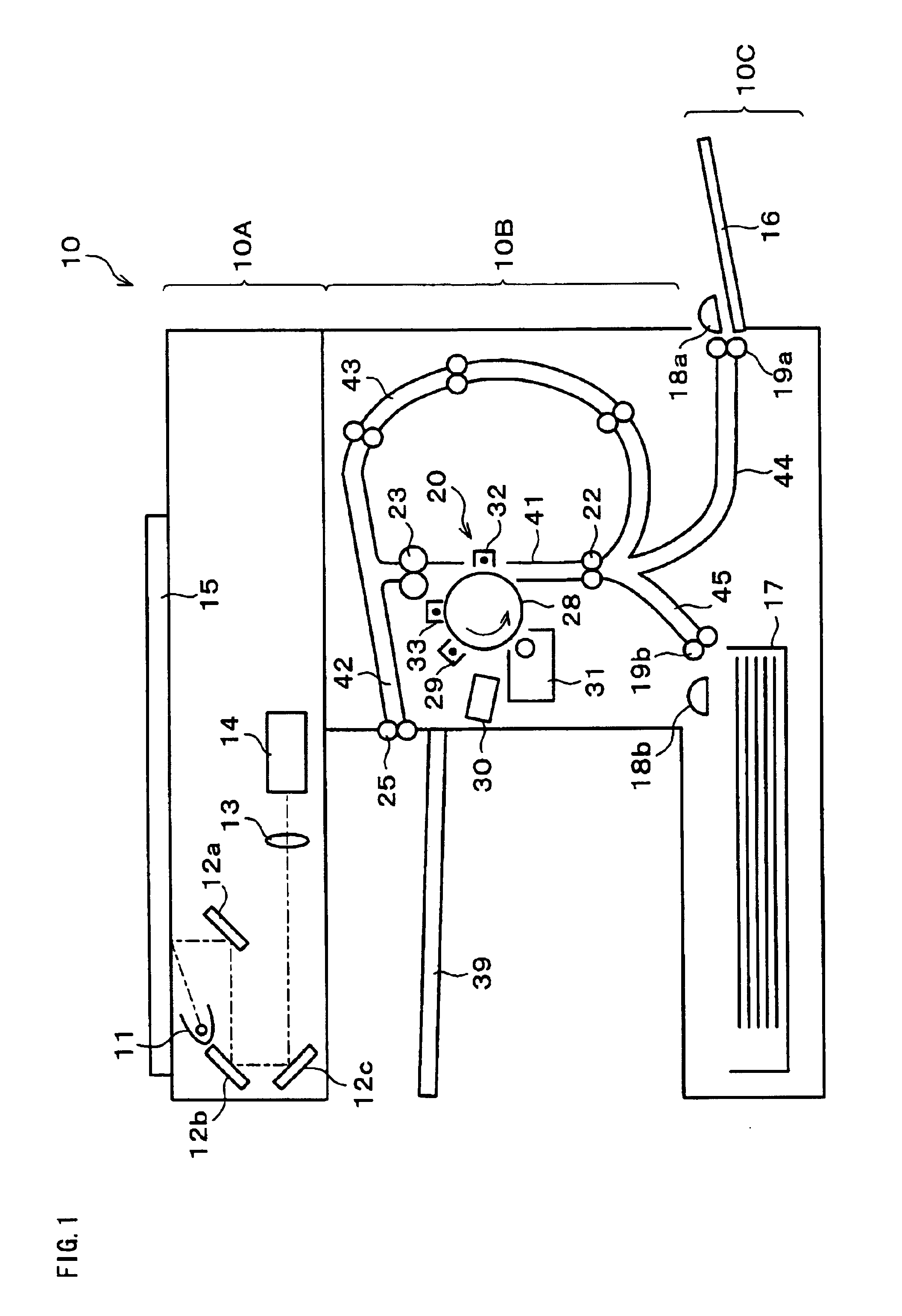
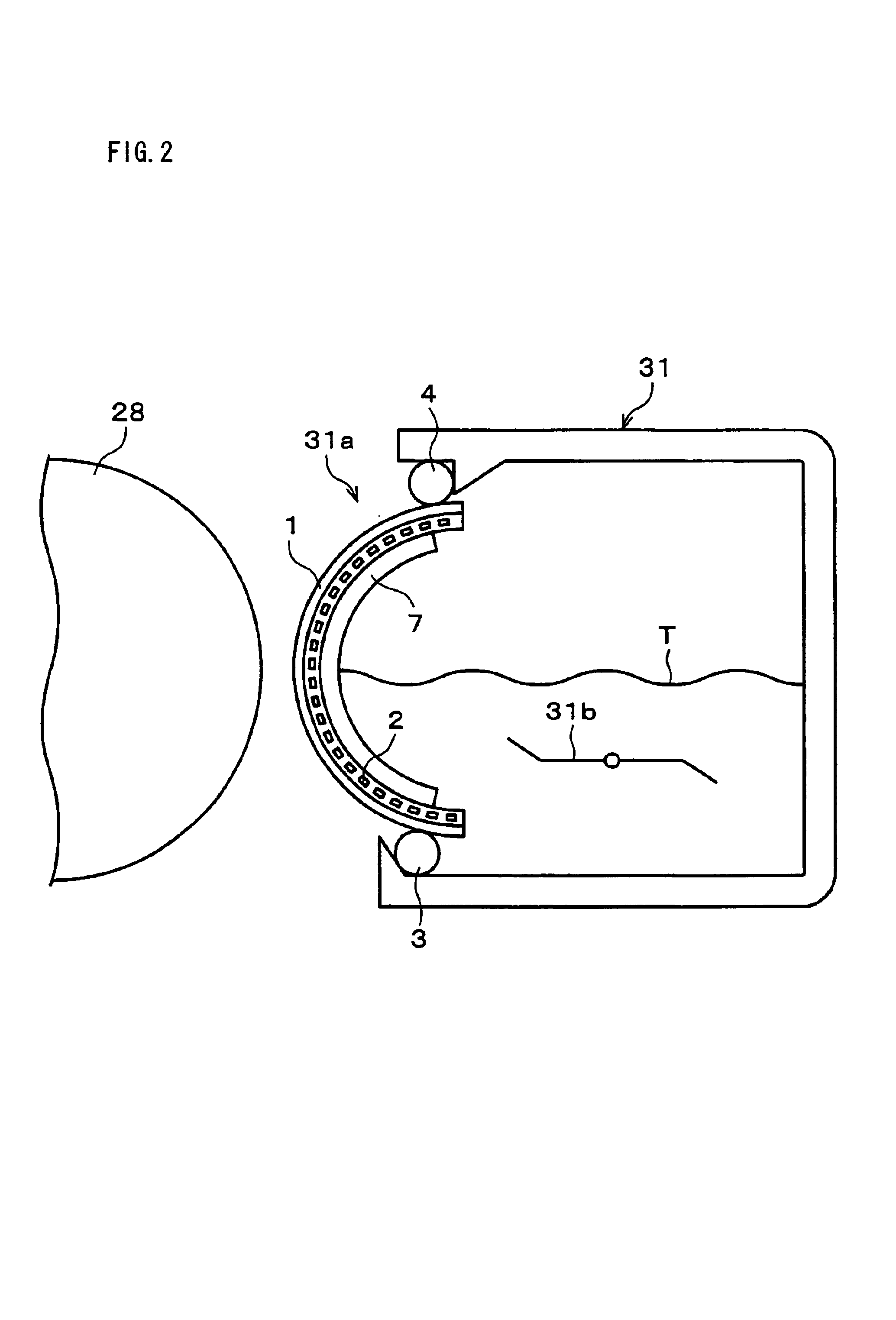
[0109]FIG. 1 is a cross-sectional view illustrating an arrangement of a digital copying apparatus, which is an example of an image forming apparatus in which a developing apparatus of an embodiment of the present invention is used. A digital copying apparatus 10 includes a scanner section 10A in an upper part thereof, a printer section 10B in a middle part thereof, and a feeding section 10C in a lower part thereof. The digital copying apparatus 10 is substantially horseshoe-shaped. The scanner section 10A has a document table 15 made of transparent hard glass. The document table 15 is exposed on an upper surface of the digital copying apparatus 10. Below the document table 15, a light source lamp 11, mirrors 12a to 12c, a lens 13, and a photoelectric conversion element (hereinafter “CCD”) 14 are provided.

[0110]The exposure lamp 11, which, together with and the mirror 12a, moves back and forth in parallel with a lower surface of the document table 15, so as to emit light onto an imag...


PUM


Abstract

On surfaces of insulating layers 1b and 1c of a transportation member 1, a protective layer 1d having a volume resistivity of 1010 Ω·cm to 1017 Ω·cm is so laminated that a sum of thickness of the insulating layers 1b and 1c is less than intervals between adjacent ones of progressive wave generating electrodes 2. With this arrangement, it is ensured that a progressive wave electric field generated by the progressive wave generating electrodes 2 is exposed beyond a surface of the transportation member 1. Even if developer T and the transportation member 1 contact each other, a surface potential of the transportation member 1 is not changed. Moreover, firm adhering of the toner T to the surface of the transportation member 1 is prevented. It is therefore possible to certainly transport the developer T to a development position always stably.

Description

TECHNICAL FIELD[0001]The present invention relates to a developing apparatus used in an electrophotographic image forming apparatus, and relates to the image forming apparatus. The developing apparatus is so arranged that an electrostatic latent image formed on an image supporting body is visualized by using developer. The present invention especially relates to a developing apparatus so arranged that developer is transported to a development position on an image supporting body by using a progressive wave electric field, and relates to an image forming apparatus using the developing apparatus.BACKGROUND ART[0002]The present invention relates to a developing apparatus used in an electrophotographic image forming apparatus. The developing apparatus is so arranged that an electrostatic latent image formed on an image supporting body is visualized by using developer. The present invention especially relates to a developing apparatus so arranged that developer is transported to a develo...

Claims


Application Information

Patent Timeline
Patent Type & Authority Patents(United States)
IPC IPC(8): G03G15/08
CPCG03G15/08G03G15/0818G03G2215/0656G03G2215/0653G03G2215/0651
Inventor SAKUMA, MASAMITSUADACHI, KATSUMIKAMIMURA, TAISUKETOIZUMI, KIYOSHIGOTOH, TOSHIMITSU
Owner SHARP KK
Why Eureka
Try Eureka