Inertial temperature control system and method

a temperature control system and temperature control technology, applied in the direction of adaptive control, electric controllers, instruments, etc., can solve the problems of delay, delay or lag, early failure of semiconductor chips manufactured from wafers,

Inactive Publication Date: 2005-05-31
AVIZA TECHNOLOGY INC
View PDF18 Cites 14 Cited by
  • Summary
  • Abstract
  • Description
  • Claims
  • Application Information

AI Technical Summary

Benefits of technology

[0010]An additional embodiment of the present invention provides a method of changing the temperature of a body housed in a heating chamber in a temperature controlled furnace from a starting to an ending temperature using a temperature control algorithm that includes the following steps. Temperature data from one or more temperature sensing devices placed in the heating chamber and a temperature set point are provided as inputs to the temperature control algorithm. The temperature control algorithm controls power delivery to one or more controllable heating elements in the furnace. The temperature set point accelerates from the starting set point temperature at a finite programmed acceleration rate until a defined maximum temperature ramp rate is achieved. Then, the set point temperature is maintained at the maximum temperature ramp rate until the ending temperature is approached. Finally, the temperature set point is decelerated from the maximum ramp rate at a finite programmed deceleration rate until the ending set point temperature is reached. This deceleration is carried out in a manner that causes the temperature of the body to reach the ending set point temperature smoothly without substantially overshooting or oscillating about the ending set point temperature.
[0011]Another embodiment of the current invention provides a temperature controlled furnace for changing the temperature of a body. The furnace includes a heating chamber housing one or more controllable heating elements and one or more temperature sensing devices. Power delivery to the heating elements is controlled by a temperature controller configured to receive a set point temperature profile and temperature data inputs representative of temperature sensing devices housed in the heating chamber. The temperature controller provides heating power commands to ramp the temperature of the body through a temperature acceleration phase, a constant ramp rate phase, and a temperature deceleration phase to achieve a desired temperature substantially smoothly with minimal oscillation around the desired temperature.

Problems solved by technology

Excessive heating of the edge of a wafer relative to its center can result in physical and / or chemical damage that could render the wafer unuseable or lead to early failure of semiconductor chips manufactured from the wafer.
The result is a time delay after the start of heating before the object's actual temperature ramp rate achieves the desired ramp rate.
The time delay or lag in the beginning of the ramp phase, overshooting of the desired setpoint, and temperature oscillations about the setpoint that are associated with prior art control methods as shown in FIG. 1 are undesirable in many applications when stable and precise temperature control is required.

Method used


Image

  • Inertial temperature control system and method
  • Inertial temperature control system and method
  • Inertial temperature control system and method

Examples


Embodiment Construction

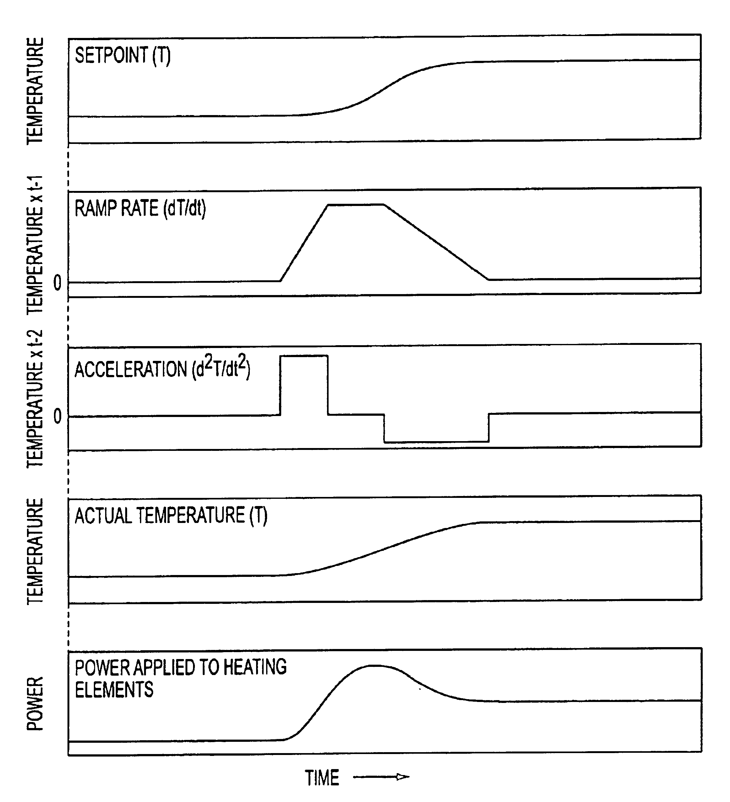
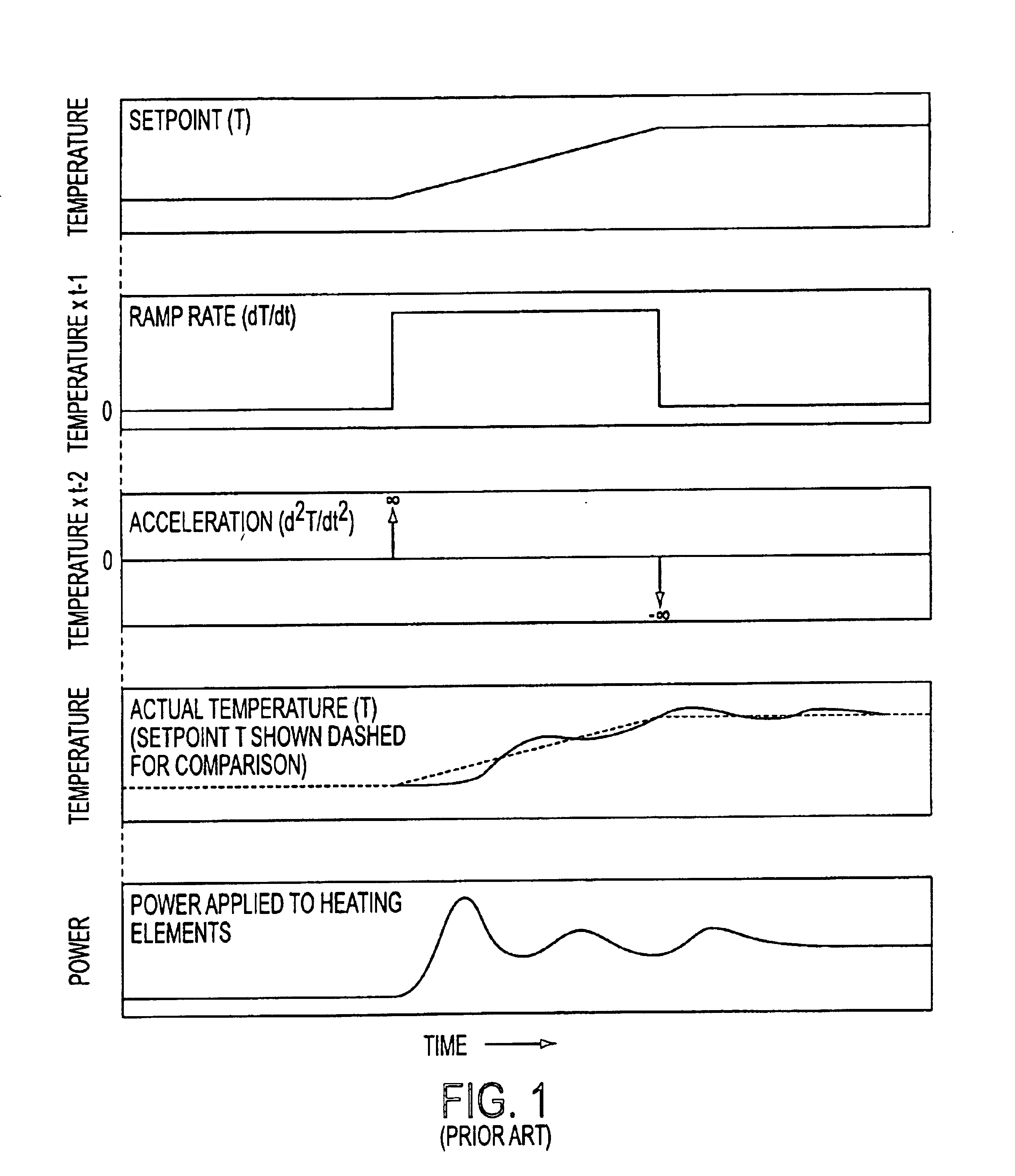
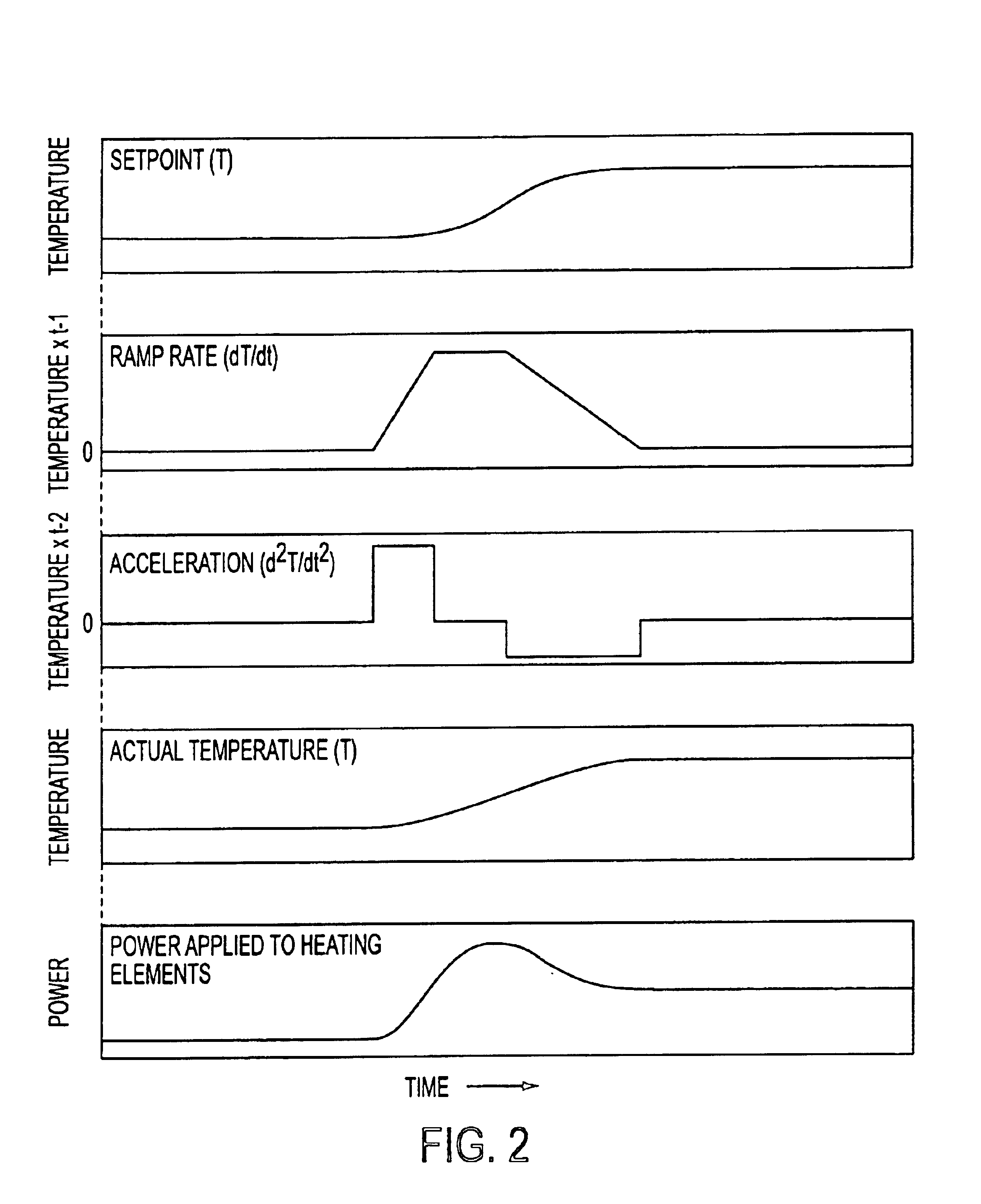
[0021]The ideas involved in inertial temperature control of the present invention have to do with how the temperature set point is managed. In prior art temperature control methods used in the semiconductor industry, an object or a body, such as a semiconductor wafer, is typically temperature ramped in a linear fashion. The actual temperature of the body cannot match the linear ramp rate, so it lags at the start, and overshoots at the end. In contrast, the present invention provides a temperature set point vs. time curve that more closely matches the curve that a real object is capable of following. Thus, the present invention accounts for the “inertial” nature of temperature changes, and controls the set point to allow the actual temperature of a body to follow the set point more closely and thereby minimize overshoot while achieving temperature stability more rapidly than prior art straight linear ramp methods.

[0022]Heat applied to a body does not instantaneously transfer to that ...


PUM


Abstract

An inertial temperature control system and method are provided for changing the temperature of a body between two temperatures such that the ending temperature is reached smoothly without substantial temperature overshoot or oscillation. A temperature control algorithm is fed a set point temperature that accelerates and decelerates at a physically attainable rate.

Description

CROSS REFERENCE TO RELATED APPLICATION[0001]This application claims the benefit of provisional application Ser. No. 60 / 266,926, filed Feb. 6, 2001, the disclosure of which is hereby incorporated by reference in its entirety.FIELD OF THE INVENTION[0002]This invention relates to a temperature control system and method used to change from one setpoint temperature to another. More specifically, the present invention relates to an inertial temperature control system and method used in a manufacturing process, such as but not limited to, semiconductor manufacturing processes and equipment.BACKGROUND OF THE INVENTION[0003]Temperature control systems and methods play a vital role in many manufacturing processes. Current state of the art methods of controlling temperature in manufacturing process employ temperature control algorithms such as Proportional, Integral, Derivative (PID) algorithms or fuzzy logic. The PID algorithm is well known in control theory, and uses the difference between t...

Claims


Application Information

Patent Timeline
Patent Type & Authority Patents(United States)
IPC IPC(8): G05D23/19H01L21/00H05B1/02G05B11/42
CPCG05D23/1935H05B1/0233H01L21/67248G05B11/42
Inventor STARNER, ALAN L.
Owner AVIZA TECHNOLOGY INC
Why Eureka
Try Eureka