Work assembling auxiliary appratus and work assembling method

a technology of auxiliary devices and work, which is applied in the direction of manufacturing tools, machines/engines, transportation and packaging, etc., can solve the problem of not being able to engage the means

Inactive Publication Date: 2005-10-13
HONDA MOTOR CO LTD
View PDF3 Cites 8 Cited by
  • Summary
  • Abstract
  • Description
  • Claims
  • Application Information

AI Technical Summary

Benefits of technology

[0005] The present invention has been accomplished with the above circumstances in view, and it is an object of the present invention to ensure that even if a somewhat deviation exists between the axis of the to-be-engaged means provided in the rotary shaft of the work body and the axis of the engage means of the work-assembling auxiliary device, the engage means can be reliably brought into engagement with the to-be-engaged means. It is another object of the present invention to ensure that in spline-coupling the end of the crankshaft of the engine and the end of the main shaft of the transmission to each other, the matching of phases in the spline-coupling can be carried out easily and reliably.
[0008] When the rotation of the input shaft through a predetermined angle and the stoppage of the member for a predetermined time are conducted alternately and repeatedly from this state by the drive means, a driving force is transmitted to the output shaft moved radially in parallel to the input shaft by the action of the coupling, and at the moment the phase of the engage means mounted on the rotating output shaft is matched with the phase of the to-be-engaged means, the engage means is engaged with the to-be-engaged means by the biasing force of the second repulsively biasing means. As described above, the engage means of the output shaft can be reliably engaged with the to-be-engaged means of the rotary shaft only by positioning the axis of the output shaft and the axis of the rotary shaft roughly rather than accurately, and moreover, the rotation of the input shaft can be reliably transmitted to the output shaft by the action of the coupling.
[0010] With the above arrangement, even if the axis of the output shaft having the follower cylindrical member fixed thereto is deviated from the axis of the input shaft having the driving cylindrical member fixed thereto, the first guide pin mounted on the driving cylindrical member is slid in a slide block, and the second guide pin mounted on the follower cylindrical member perpendicularly to the first guide pin is slid in the slide block, whereby the rotation of the input shaft can be transmitted to the output shaft without hindrance.
[0016] With the above arrangement, the hydraulic and pneumatic pressure converter for converting the pneumatic pressure into the hydraulic pressure is interposed between the pneumatic pressure source and the drive means comprising the hydraulic cylinder. Therefore, the drive means can be driven at a constant speed irrespective of the magnitude of a load to prevent the rapid rotation of the output shaft. Moreover, an influence of a difference between the area of a piston of the hydraulic cylinder adjacent the output rod and the area of the piston on the side opposite from the output rod and other problems attendant on the compressibility of air can be eliminated by the action of the hydraulic and pneumatic pressure converter.
[0024] With the above feature, the crankshaft is rotated for reciprocation by the drive means and hence, the phase-matching operation on the side of the spline of the main shaft can be simplified to smoothly achieve the spline coupling.
[0026] With the above feature, the crankshaft is rotated intermittently in one direction by the drive means and hence, the phase-matching operation on the side of the spline of the main shaft can be simplified to smoothly achieve the spline coupling.

Problems solved by technology

However, in many cases, the engage means cannot be engaged with the to-be-engaged means due to the mismatching of their phases, and the second repulsively biasing means is compressed to generate a biasing force in a direction to permit the engagement of the engage means with the to-be-engaged means.

Method used


Image

  • Work assembling auxiliary appratus and work assembling method
  • Work assembling auxiliary appratus and work assembling method
  • Work assembling auxiliary appratus and work assembling method

Examples


Embodiment Construction

[0043] The present invention will now be described by way of an embodiment of the present invention with reference to the accompanying drawings.

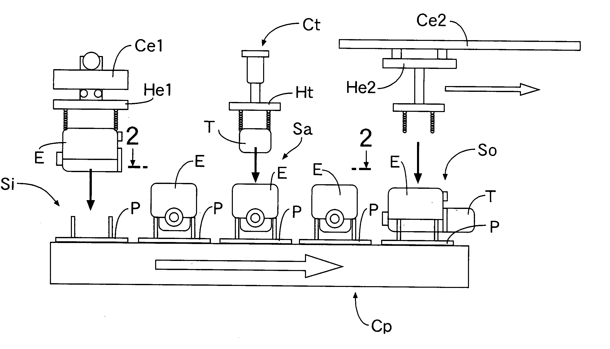
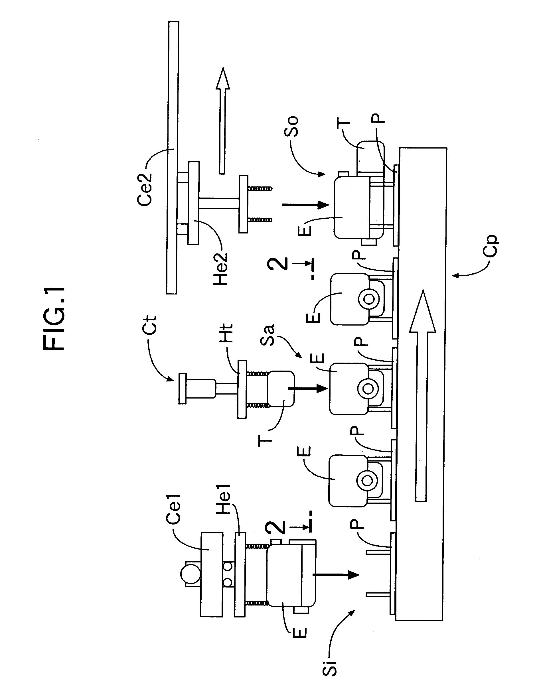
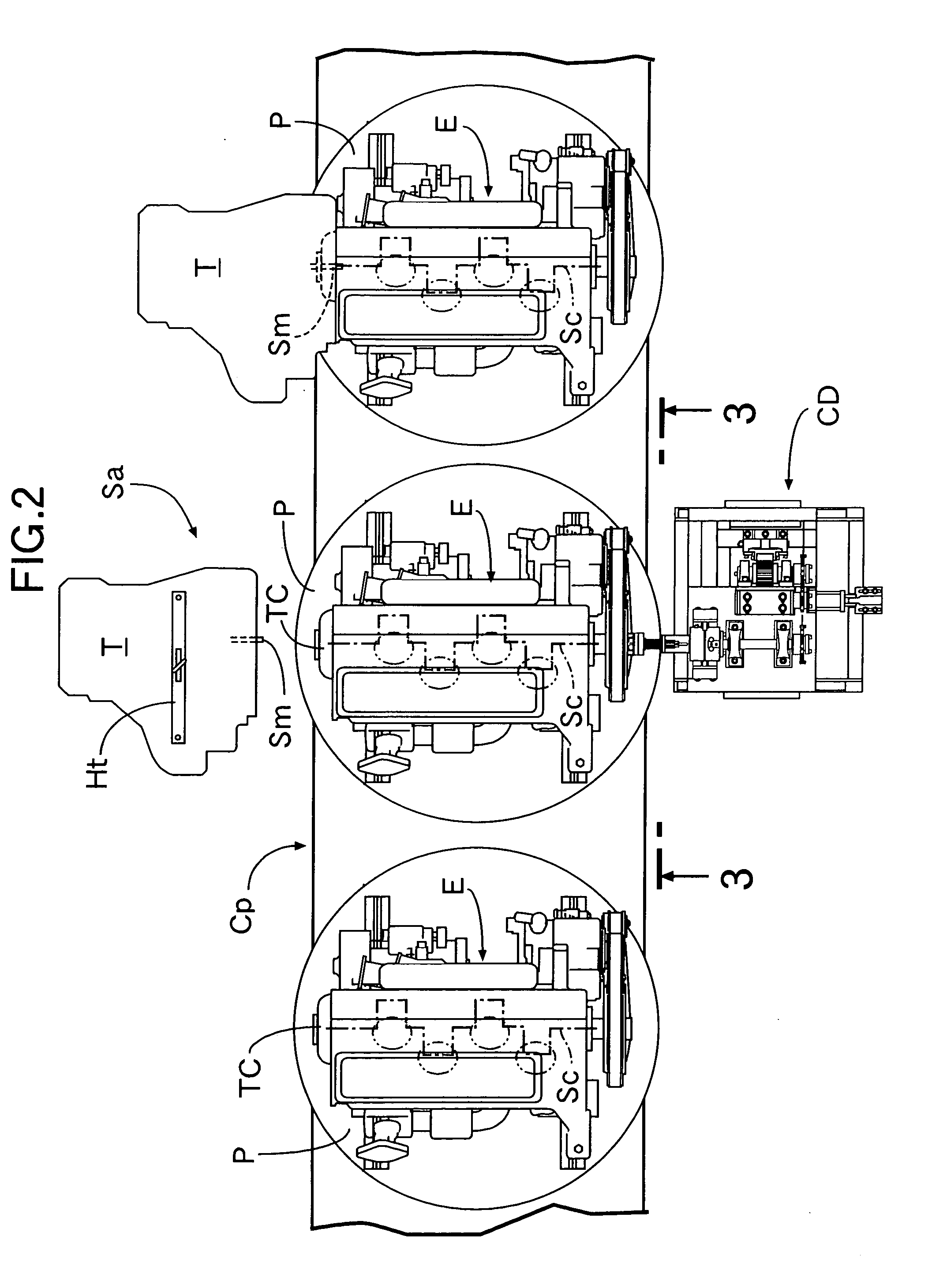
[0044] Referring to FIG. 1, a take-in station Si, a transmission-assembling station Sa and a take-out station So are provided in a transporting path in a pallet conveyor Cp for transporting a pallet P having an engine E placed thereon. An engine E assembled in an engine-assembling line is hung down by a hanger He1 of an engine taking-in overhead conveyor Ce1 and transported into the take-in station Si, where the engine E is transferred onto the pallet P on the pallet conveyor Cp. A transmission T assembled in a transmission-assembling line is hung down by a hanger Ht of a transmission taking-in overhead conveyor Ct and transported into the transmission-assembling station Sa, where the transmission T is assembled to the engine E. The engine E having the transmission T assembled thereto is transported to the take-out station So by the pallet ...


PUM

PropertyMeasurementUnit
angleaaaaaaaaaa
rotational angleaaaaaaaaaa
rotational forceaaaaaaaaaa

Abstract

A work-assembling auxiliary device for carrying out the matching of phases in the spline-coupling of a main shaft Sm of a transmission T to a crankshaft Sc of an engine E includes an output shaft 40 radially movably connected through an Oldham coupling 41 to an input shaft 30 connected to and rotated by a drive source. A chamfer 61a is provided at a tip end of a socket 61 mounted on the output shaft 40, and in inserting the socket 61 into a socket hole h in a crank pulley Pc, the output shaft 40 is smoothly aligned with the crankshaft Sc by the action of the chamfer 61a. Further, when the output shaft 40 is reciprocally rotated, the phases of the socket 61 and the socket hole h are smoothly matched with each other, whereby the engagement of the socket 61 and the socket hole h is achieved. Thus, even if a somewhat deviation exists between an axis of the crankshaft Sc of the engine E and an axis of the output shaft 40 of the work-assembling auxiliary device, the socket 61 of the output shaft 40 can be reliably engaged into the socket hole h in the crankshaft Sc.

Description

FIELD OF THE INVENTION [0001] The present invention relates to a work-assembling auxiliary device including an engage means capable of being brought into engagement with a to-be-engaged means provided in a rotary shaft of a work body to transmit a rotating force of a drive means to the rotary shaft of the work body through the engage means and the to-be-engaged means, and to a work-assembling process for assembling an engine and a transmission in an assembling line. BACKGROUND ART [0002] One example of means for carrying out an assembling operation by rotating the rotary shaft of the work body to adjust the phase of the rotary shaft is a transmission-assembling station provided in a power unit-assembling line for an automobile. When an engine assembly and a transmission assembly assembled in the assembling line are to be integrally coupled to each other, an end of a main shaft of the transmission assembly is spline-coupled into a shaft hole in a crankshaft of the engine assembly. In...

Claims


Application Information

Patent Timeline
Patent Type & Authority Applications(United States)
IPC IPC(8): B23P19/00B23P21/00B62D65/10F02B63/00F02B77/00F02F7/00
CPCB23P19/10F02B63/00F02B77/00F02F7/0046Y10T29/4978Y10T29/49231Y10T29/49286Y10T29/4984Y10T29/53Y10T29/49778
Inventor TATEISHI, TAKEYAYOKOMUKAI, TAKU
Owner HONDA MOTOR CO LTD
Why Eureka
Try Eureka