Balancing apparatus for rotating bodies, in particular tool-carriers with tools rotating at high speed

a technology of rotating bodies and balancing apparatus, which is applied in the direction of maintenance and safety accessories, structural/machine measurement, instruments, etc., can solve the problems of unbalance, limited balancing accuracy, and the solution itself has a relatively important bulkiness, so as to reduce the bulkiness, reduce the cost, and the effect of accurate balancing

Inactive Publication Date: 2005-06-07
BALANCE SYST
View PDF4 Cites 4 Cited by
  • Summary
  • Abstract
  • Description
  • Claims
  • Application Information

AI Technical Summary

Benefits of technology

[0025]It is an important aim of the invention to provided an automatic balancing apparatus of the type involving rings, capable of carrying out, with a reduced bulkiness and reduced costs, an accurate balancing of rotating bodies, even of bodies adapted to rotate at very high speeds, in the order of 40,000-50,000 revolutions per minute.
[0026]It is a further important aim of the invention to provide an apparatus of the type in question enabling a calculated and controlled angular positioning of the balancing rings without limitations and also over very small portions, so as to obtain a very fine adjustment of the rings and therefore a great balancing accuracy.
[0027]Another aim of the invention is to provide an apparatus of the above kind, offering a higher balancing capability than known apparatus, without increasing the bulkiness of the apparatus.
[0028]A still further aim of the invention is to devise a balancing apparatus enabling the axial bulkiness of the balancing rings to be maintained to a minimum so as to avoid dynamic unbalances in the axial plane of the rotating body.
[0029]Another aim of the invention is to provide a balancing apparatus enabling the balancing rings to be acted upon without mutual interference, even in the case of very close rings.
[0031]Another aim of the invention is to provide an apparatus that can be easily applied to machine tools already in use.

Problems solved by technology

These rings can be angularly rotated relative to the rotating body, during rotation of the latter, to such a position as to compensate, with the resultant of their unbalance, for the residual unbalance of the rotating body.
In this technical solution however, the balancing accuracy is limited because balancing is carried out for discrete angles depending on the pitch between the permanent magnets that cannot be reduced beyond predetermined limits.
The solution itself has a relatively important bulkiness and in any case has strong limitations to miniaturization.
Other drawbacks of these apparatus in which the rings are operated electromagnetically are the following.
The presence of the electric windings may involve interferences in the individual control of the rings during the balancing step, because the magnetic field acting on one of the rings may affect the magnetic field acting on the other ring, so that achievement of the right angular balancing position of the rings is made more difficult.
It is therefore necessary to keep some axial distance between the rings and between the respective windings, but a greater axial distance may lead to dynamic unbalances, because it can generate an undesirable torque in the axial plane of the rotating body due to the unbalanced rings being spaced apart too much.
Another drawback of these apparatus having an electromagnetic control resides in that they can magnetically attract metal scraps or chips or other ferrous materials removed during working, that will tend to accumulate in the regions where the magnetic field is present and to alter the magnetic field itself or form dangerous deposits, in particular at the air gap, which can stop the mechanisms and seriously jeopardize a good operation of the balancing apparatus.
In addition, these apparatus can be hardly applied to pre-existing machines.
On the other hand, it has been found that in a practical application the working vibrations and sudden accelerations and decelerations of the rotating body can cause undesirable slow angular displacements of the rings and this may need some balancing corrections.
To avoid these displacements that can also take place in apparatus with an electromagnetic control of the rings, the rings should be mounted with more friction on the rotating body, but this would make the angular positioning of same more difficult and the balancing result less accurate.
In addition, the system for control of the compressed air through the nozzles can have some management difficulties and therefore can involve a more complicated control electronics.

Method used


Image

  • Balancing apparatus for rotating bodies, in particular tool-carriers with tools rotating at high speed
  • Balancing apparatus for rotating bodies, in particular tool-carriers with tools rotating at high speed
  • Balancing apparatus for rotating bodies, in particular tool-carriers with tools rotating at high speed

Examples


Embodiment Construction

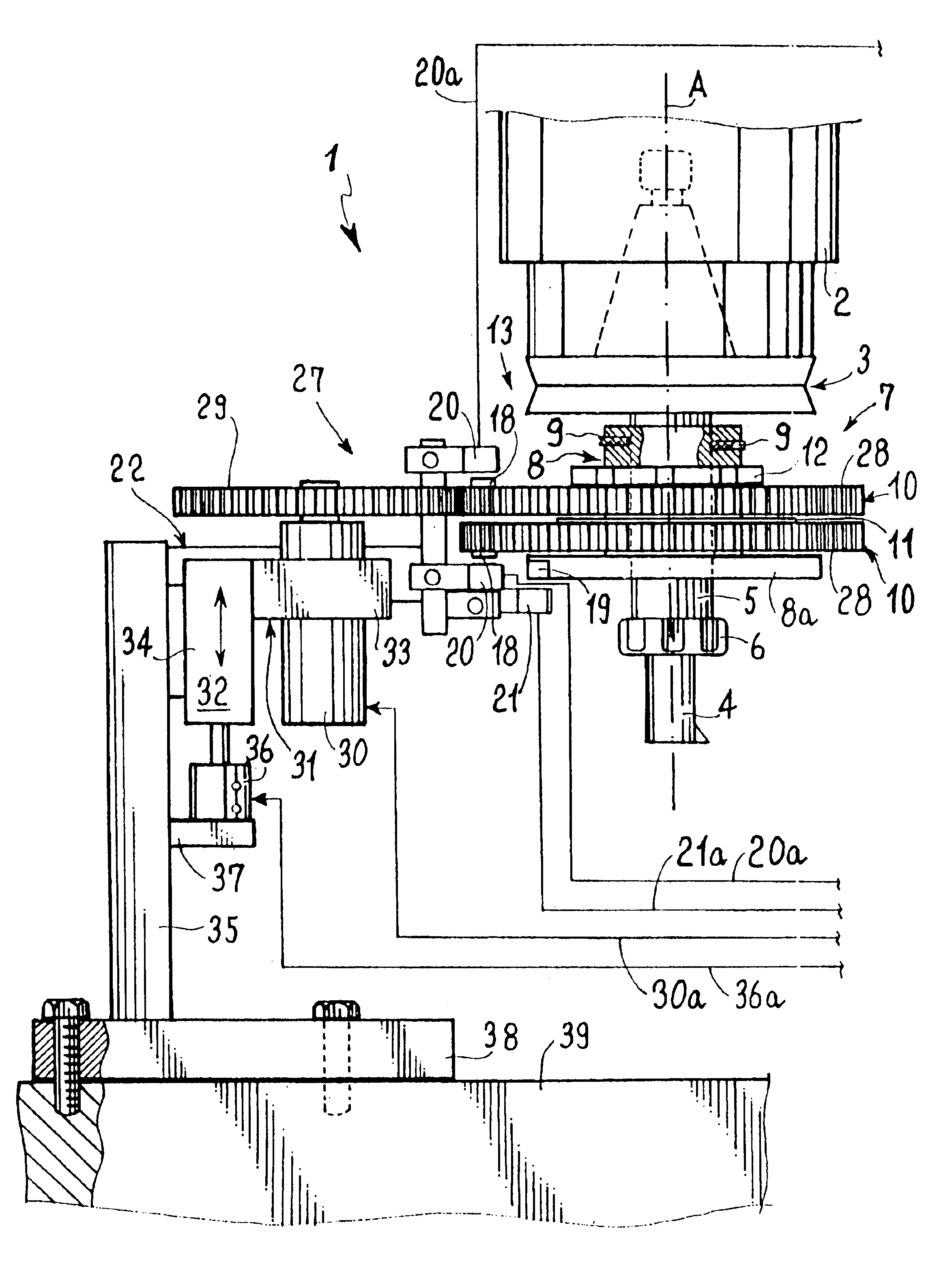
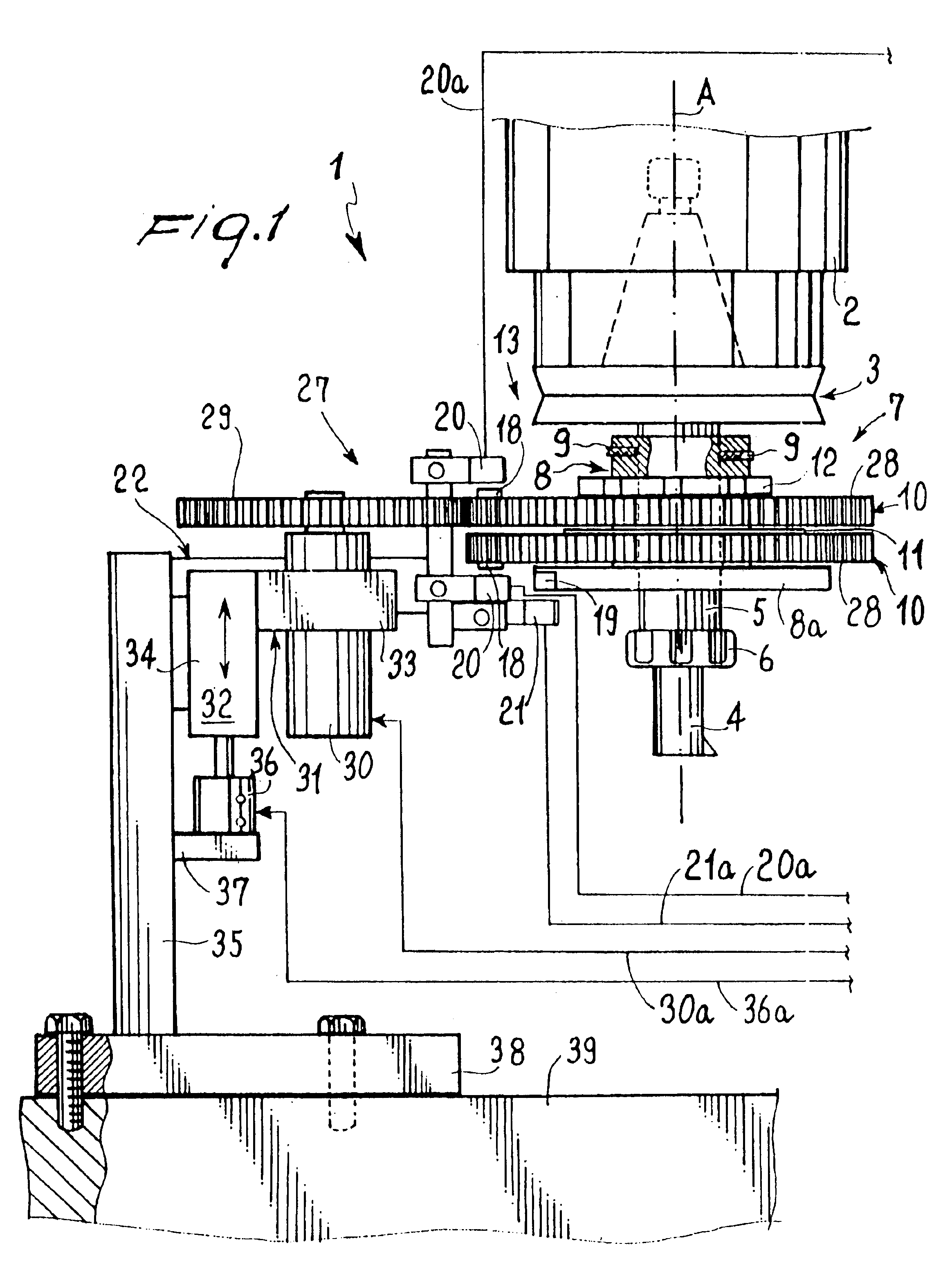
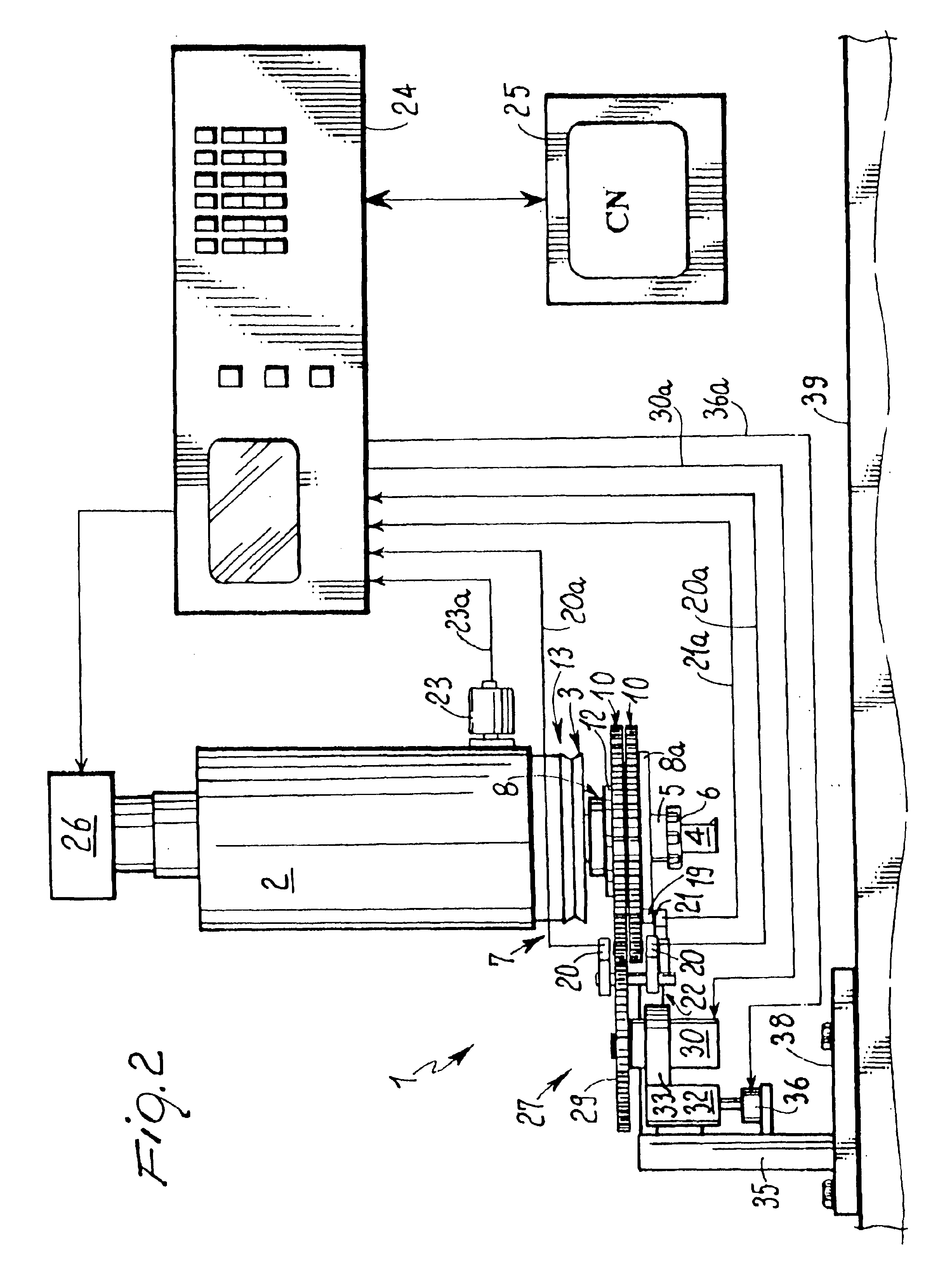
[0042]With reference to the drawings, a balancing apparatus for rotating bodies in accordance with the invention is generally identified by reference numeral 1. In the embodiments shown in FIGS. 1 to 4 it is applied, by way of example, to a work center such as a machine tool. Of this machine, shown in the drawings is a spindle 2 that through a tool-carrier 3 of known type carries a tool 4 fastened to the tool-carrier shaft 5 through a locking ring nut 6.

[0043]Mounted on shaft 5 is a balancing head, generally denoted at 7 and comprising a central hub 8 fastened to shaft 5 by locking dowels 9 for example and fixedly carrying an end flange 8a.

[0044]A pair of coaxial balancing rings 10 disposed in axial side by side relationship is disposed on hub 8 and an annular spacer 11 with a friction function is interposed therebetween.

[0045]Rings 10 are mounted on hub 8 by interposition of friction elements that are preloaded with Belleville washers, undulated springs or the like, not shown, so ...


PUM

PropertyMeasurementUnit
relative angular rotationaaaaaaaaaa
frictionaaaaaaaaaa
rotation axisaaaaaaaaaa

Abstract

The apparatus (1) comprises at least two balancing rings (10) disposed in axial side by side relationship and coaxial with each other on the rotating body (13) to be balanced. The rings (10) are each unbalanced and rotatable with the rotating body (13), but can each be angularly rotated relative to the latter through positioning members. These members may comprise either a gear (29) that can be selectively engaged in rotation with peripheral toothings (28) of the rings (10) when the rotating body (13) is stopped, to bring the rings (10) to a relative angular position to which the situation of balance of the rotating body (13) corresponds, or locking elements to be selectively engaged with peripheral notches in the rings (10) to retain the rings (10) one by one while the rotating body (13) is rotated relative to the rings (10) through such an angle that the angular balance position is achieved.

Description

FIELD OF THE INVENTION[0001]The invention relates to a balancing apparatus for rotating bodies, in particular tool-carriers with tools rotating at high speed.[0002]It is known that current machine tools are able to remove material at very high cutting speeds, even of 40,000 revolutions per minute and more. Under these rotation conditions balancing of the tool together with its tool-carrier mounted on the machine spindle acquires a fundamental importance.DESCRIPTION OF THE PRIOR ART[0003]In this connection apparatus are known which are capable of carrying out balancing directly on the machine, when unbalances of the tool exceeding a predetermined tolerance range are detected during working.[0004]These apparatus substantially comprise two balancing rings, disposed in axial side by side relationship and coaxial with each other on a cylindrical support rigidly fixed to the rotating body to be balanced. The rings are rotatable together with the rotating body and each have a known unbalan...

Claims


Application Information

Patent Timeline
Patent Type & Authority Patents(United States)
IPC IPC(8): G01M1/00G01M1/36
CPCG01M1/36Y10T409/304312Y10T408/76
Inventor TRIONFETTI, GIANNI
Owner BALANCE SYST
Why Eureka
Try Eureka