Porous restrictor for gas bearing

a restrictor and gas bearing technology, applied in the direction of bearings, sliding contact bearings, linear bearings, etc., can solve the problems achieve the effect of increasing local pressure, reducing the stiffness of gas bearings, and reducing the size of gas bearings

Inactive Publication Date: 2005-06-07
GLOBAL COOLING
View PDF5 Cites 39 Cited by
  • Summary
  • Abstract
  • Description
  • Claims
  • Application Information

AI Technical Summary

Benefits of technology

[0010]The space upstream of the gas bearing restrictor is the charge volume. In a preferred embodiment, the charge volume is pressurized to the maximum pressure in the Stirling cycle by the use of a small reed check valve. The charge volume bleeds through the restrictive porous strip and via the orifice to the gas bearing clearance gap and then through the clearance gap. By arranging the restrictors to have a similar restriction to the resistance of the clearance gap, it is possible to obtain close to maximum gas bearing stiffness.
[0012]The use of the plastic porous strip as a restrictor has the advantage of being multi-pathed and therefore far less likely to become blocked with loose particles. There are distributed orifices for the gas to flow through, and if one becomes blocked, it will have little effect on the gas bearing. A further advantage is that the gas bearing restrictor becomes its own filter which prevents small particles from entering the close fitting clearance seals typically found on machines that employ gas bearings.
[0013]The porous material is easily fitted into a piston sleeve by providing a backing ring or spring that squeezes the porous material against the orifices of the gas bearing. Installation could be done by an automatic machine and appears to be advantageous for high volume production.
[0014]Costs in material and labor appear to be extremely low compared to conventional techniques. Reliability is expected to be far better due to lower likelihood of blockage and prevention of particles coming into the clearance gap. This gas bearing restrictor appears particularly favorable for implementation in Stirling cycle machinery.
[0015]The proposed invention appears to offer all these advantages and has the additional advantage of providing a filter for particles that might damage or wear the close fitting bearing surfaces. Restriction performance has been found to be comparable to precision restrictors consisting of 60-micron glass capillaries of 5-mm length.

Problems solved by technology

This restricts the flow of gas locally through the clearance gap even more, which tends to increase the local pressure in the clearance gap.

Method used


Image

  • Porous restrictor for gas bearing
  • Porous restrictor for gas bearing
  • Porous restrictor for gas bearing

Examples


Embodiment Construction

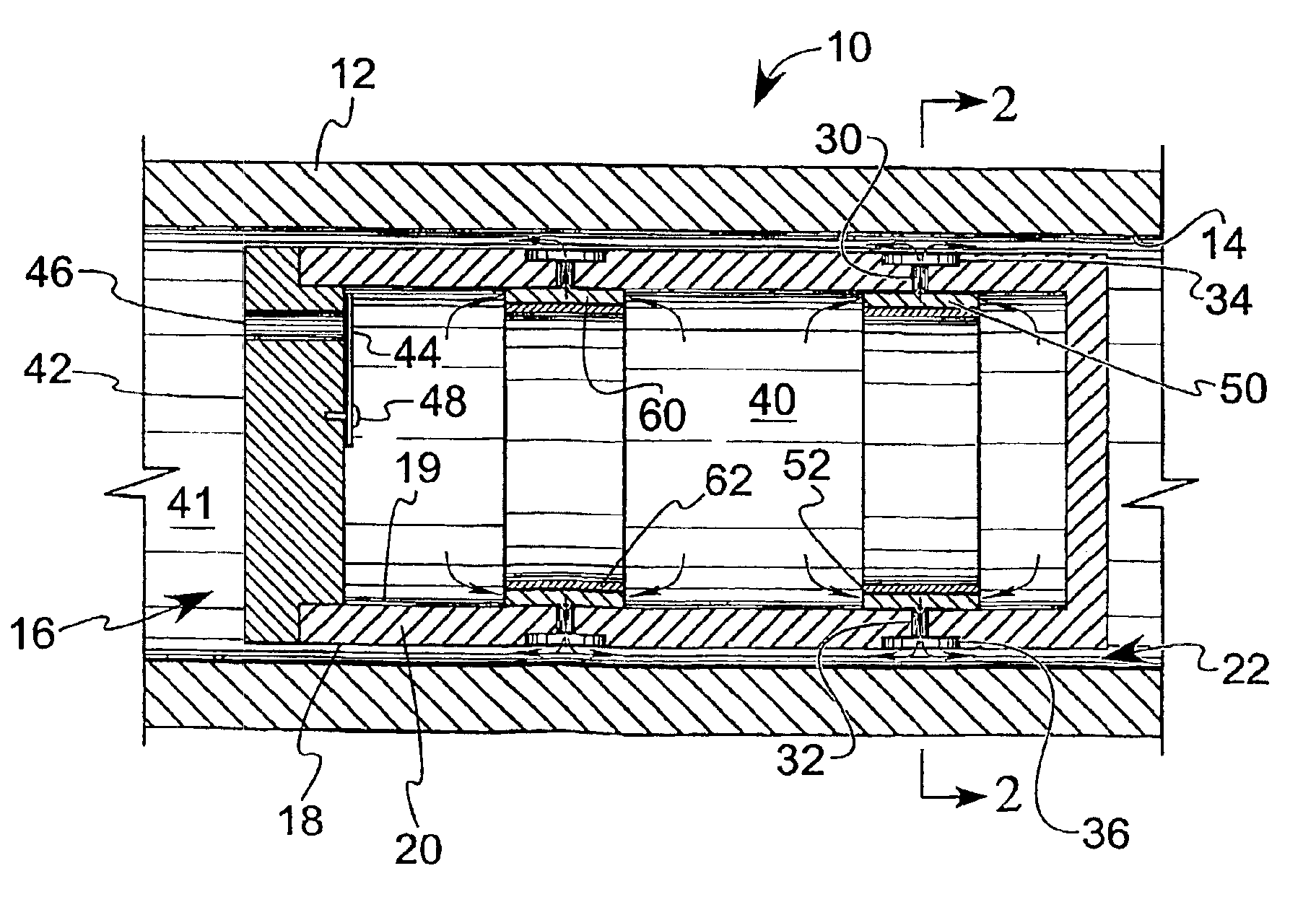
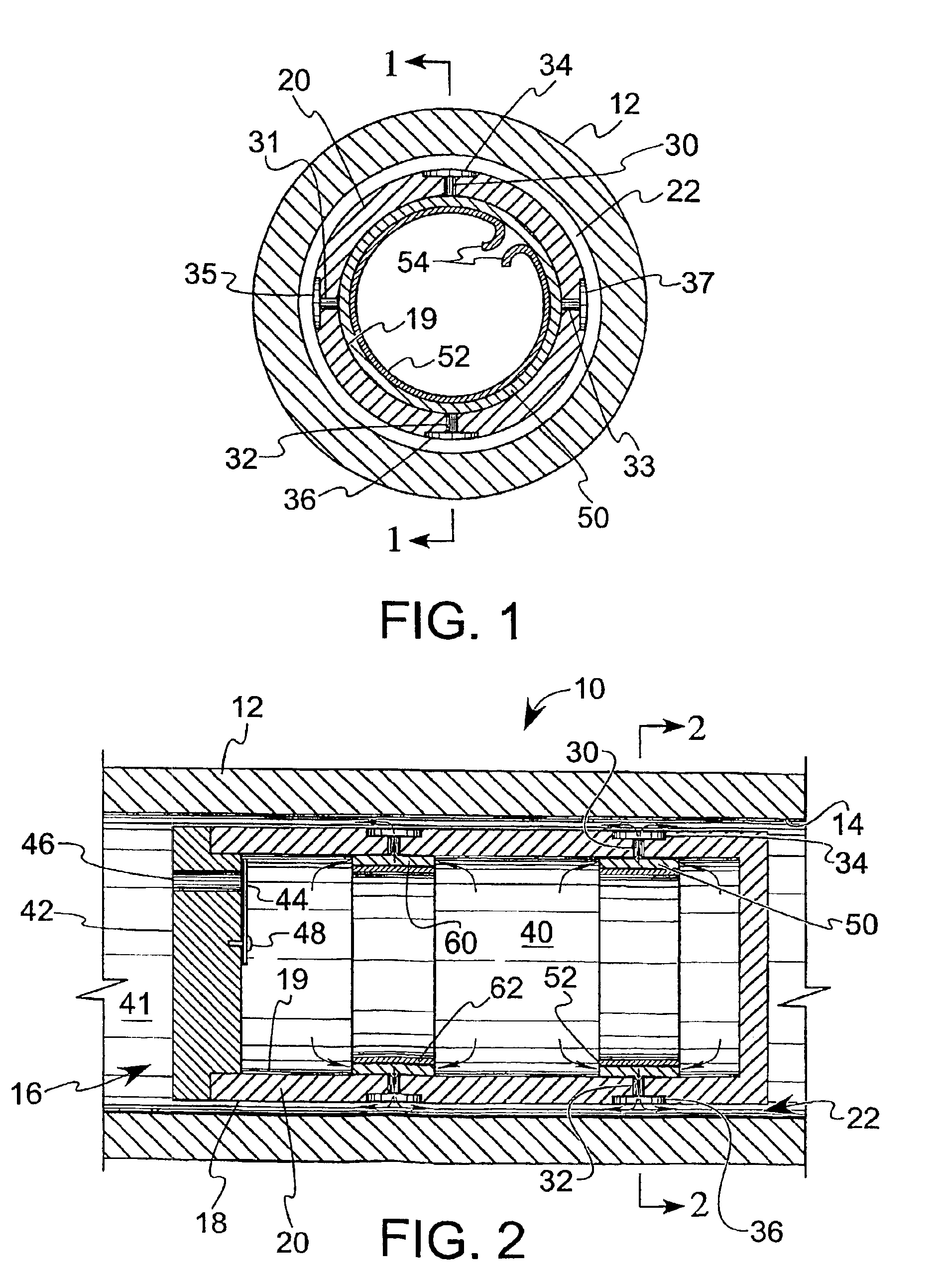
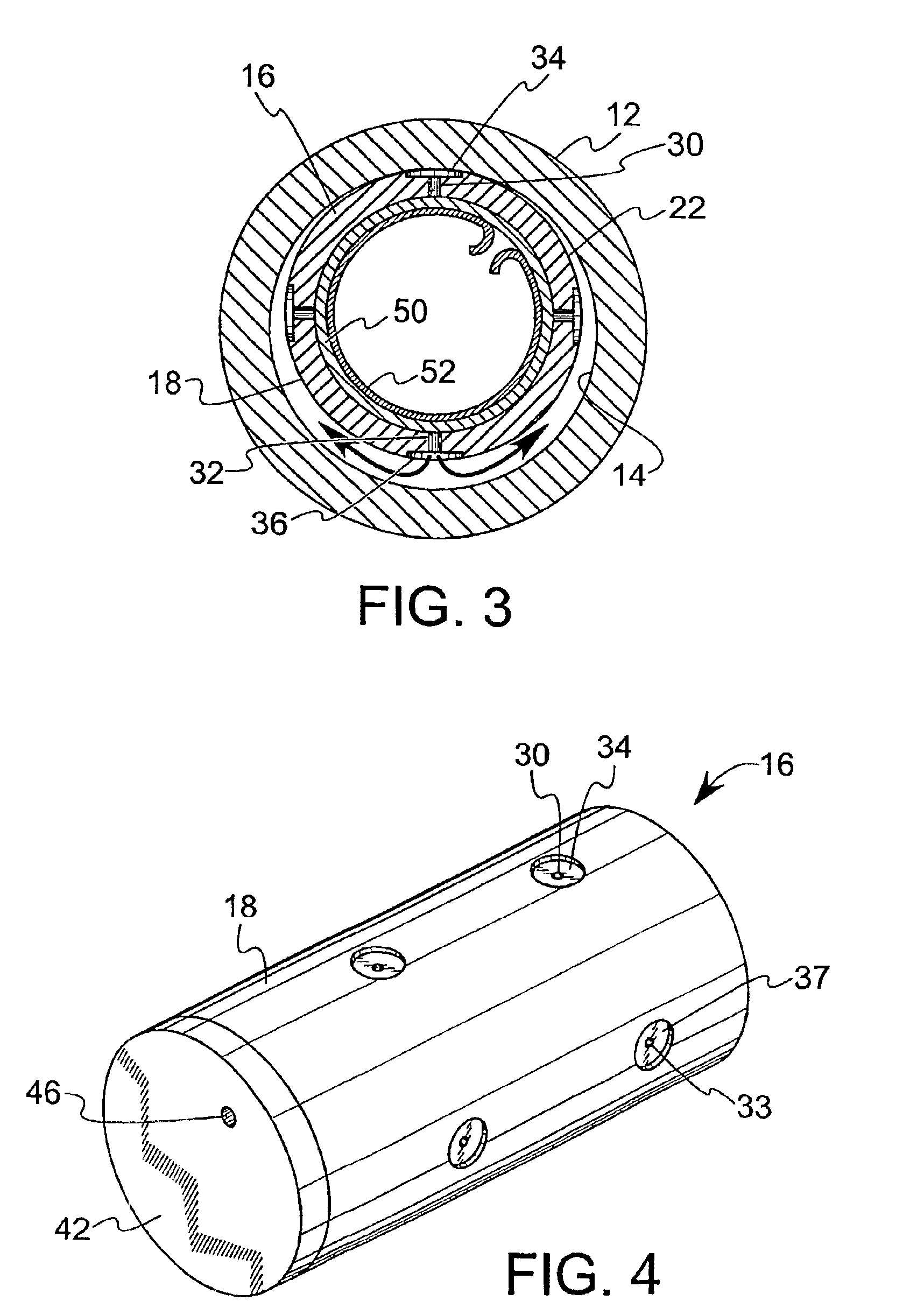
[0024]The preferred embodiment of the present invention is shown in FIG. 1, in which the free piston Stirling cycle apparatus 10 includes a cylindrical housing 12 having an internal sidewall surface 14, which is a circular cylinder. The piston 16, also shown in FIG. 4, has an outer cylindrical surface 18 on the sidewall 20 that is disposed in close proximity to the internal cylindrical surface 14 of the housing sidewall 12.

[0025]There is an annular gap 22 formed between the piston 16 and the housing 12 in which the working fluid, such as helium gas, flows. The size of the annular gap is, exaggerated in the drawings. The diametrical difference of the outer surface of the piston 16 and the housing inner surface 14 is between about 15 and 35 microns in a contemplated embodiment. Thus, the annular gap is half of that difference when the piston 16 is radial dead center (eccentricity of zero), which is 7.5 to 17.5 microns. The gas flows through the annular gap 22, thereby providing a flui...


PUM


Abstract

A gas restrictor particularly usrful for applicatio in gas bearing as used, for example, in free-piston Striling cycle machinery. Porous strip material together with a backing plate and orifice (bleed hole) is used to provide the restriction to the flow of gas into an annular gap between a piston and a cylinder.

Description

[0001]This application claims the benefit of provisional 60 / 345,472, filed on Oct. 19, 2001.BACKGROUND OF THE INVENTION[0002]1. Field Of The Invention[0003]This invention relates generally to gas bearings as used, for example, in free-piston Stirling machines, and relates more particularly to a restrictor apparatus used with gas bearings.[0004]2. Description of the Related Art[0005]In many different machines, pistons reciprocate in a cylinder formed in a housing. Due to accurate machining, a thin annular gap is formed between the cylinder wall and the piston wall. In Stirling cycle machines, for example, the housing encloses a work space bounded by one end of the piston and a back space bounded by the opposite end of the piston. The term “piston” can refer generically to any piston-like body, including the displacer in a Stirling cycle machine. A working gas, such as helium, fills the workspace, back space and other regions of the machine within the housing.[0006]Because of the clos...

Claims


Application Information

Patent Timeline
Patent Type & Authority Patents(United States)
IPC IPC(8): F01B31/10F01B31/00F02G1/043F16C29/02F16C32/06
CPCF02G1/0435F02G1/0535F16C32/0618F16C32/0603F16C29/025F16C32/0622
Inventor KIIKKA, DALE E.
Owner GLOBAL COOLING
Why Eureka
Try Eureka