Surge prevention device

a technology of a surge prevention device and a pressure regulator, which is applied in the direction of water supply installation, pressure relieving device on the sealing face, container discharging method, etc., can solve the problems of high risk of oxygen regulator failure, unsatisfactory high pressure surge, and similar problems with respect to nitrous oxide supplied, so as to avoid excessive heating and high pressure surge. , the effect of heat during gas recompression

Inactive Publication Date: 2005-06-07
ALLIED HEALTHCARE PROD INC
View PDF43 Cites 56 Cited by
  • Summary
  • Abstract
  • Description
  • Claims
  • Application Information

AI Technical Summary

Benefits of technology

[0015]The present invention also relates to a method of operating a high pressure valve. The method includes the steps of: (1) moving a handle in an enabling direction to cause gas to flow through a first path at a first flow rate; and then (2) moving the handle in a second direction to cause gas to flow through a second path at a much greater flow rate. The method also may include the step of closing the valve. According to a preferred embodiment of the invention, the method may involve flowing gas, such as oxygen or nitrous oxide, through a pressure regulator to a user or to an intended device (such as a respirator). The method may be used to gradually increase the flow rate into the regulator and to prevent the formation of a high pressure surge in the system.
[0017]The present invention further relates to a surge prevention dual-port (or dual-path) valve, which is provided with first and second valves located within a housing and integrating a pressurization orifice. The initial opening of the dual-port (or dual-path) valve in an axial direction enables a first flow of gas to flow through the pressurization orifice at a first flow rate. The fill opening of the dual-port (or dual-path) valve enables a second flow of gas to flow through the second valve at a second flow rate which is higher than the first flow rate. The controlled pressurization of the gas through the pressurization control orifice delays the time in which the gas reaches full recompression. This, in turn, allows the heat generated by the near adiabatic process of the recompression of the gas to be dispersed. This way, high pressure surges are prevented, the heat during gas recompression is dispersed and excessive heating is avoided. The present invention also relates to a method of operating the dual-port (or dual-path) valve.

Problems solved by technology

When the valves in the known oxygen systems are opened rapidly, undesirable high pressure surges may be applied to the pressure regulator.
A similar problem may occur with respect to nitrous oxide supplied, for example, for dental procedures.
The risk of oxygen regulator failure may be higher for portable oxygen systems that are used in adverse environments and / or by untrained personnel.
These devices all suffer from one or more of the following drawbacks: relatively massive pistons resulting in slower response times, relatively elongated bodies, complicated construction resulting in increased cost, or construction preventing positioning of the devices in different locations in existing systems.
Additionally, if the bleeder orifice becomes plugged, the valve does not allow flow, and the gas supply is not available for use.
In that case, the user may interpret the tank to be empty when it is full, with the danger that such a misunderstanding brings.
The elongated piston results in an increased moment of inertia that increases the time in which the piston reacts to a pressure surge.
In addition, the placement of the spring abutting the elongated piston results in a relatively large device.
The elongate construction of the piston results in an increased moment of inertia that increases the time required for the piston to react to a pressure surge.
The two-part piston results in increased complexity and manufacturing cost.
Also in this device, if the restricted passageway becomes plugged, no flow is allowed and the device suffers from the same potential for user misinterpretation as the Acomb device.

Method used


Image

  • Surge prevention device
  • Surge prevention device
  • Surge prevention device

Examples


Embodiment Construction

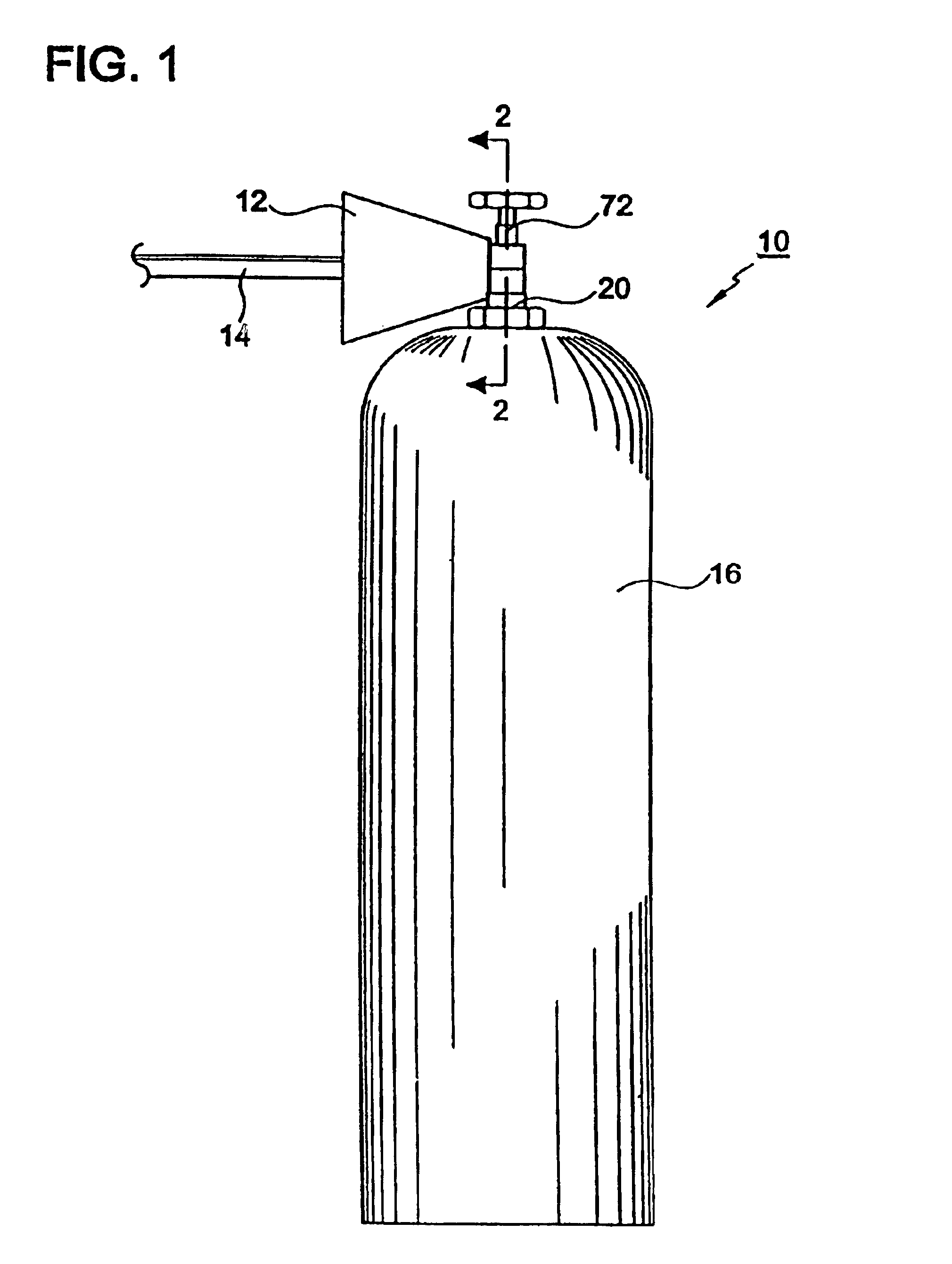
[0031]Referring now to the drawings, where like elements are designated by like reference numerals, there is shown in FIG. 1 an oxygen supply system 10 constructed in accordance with a preferred embodiment of the present invention. A detailed description of the illustrated system 10 is provided below. The present invention should not be limited, however, to the specific features of the illustrated system 10.

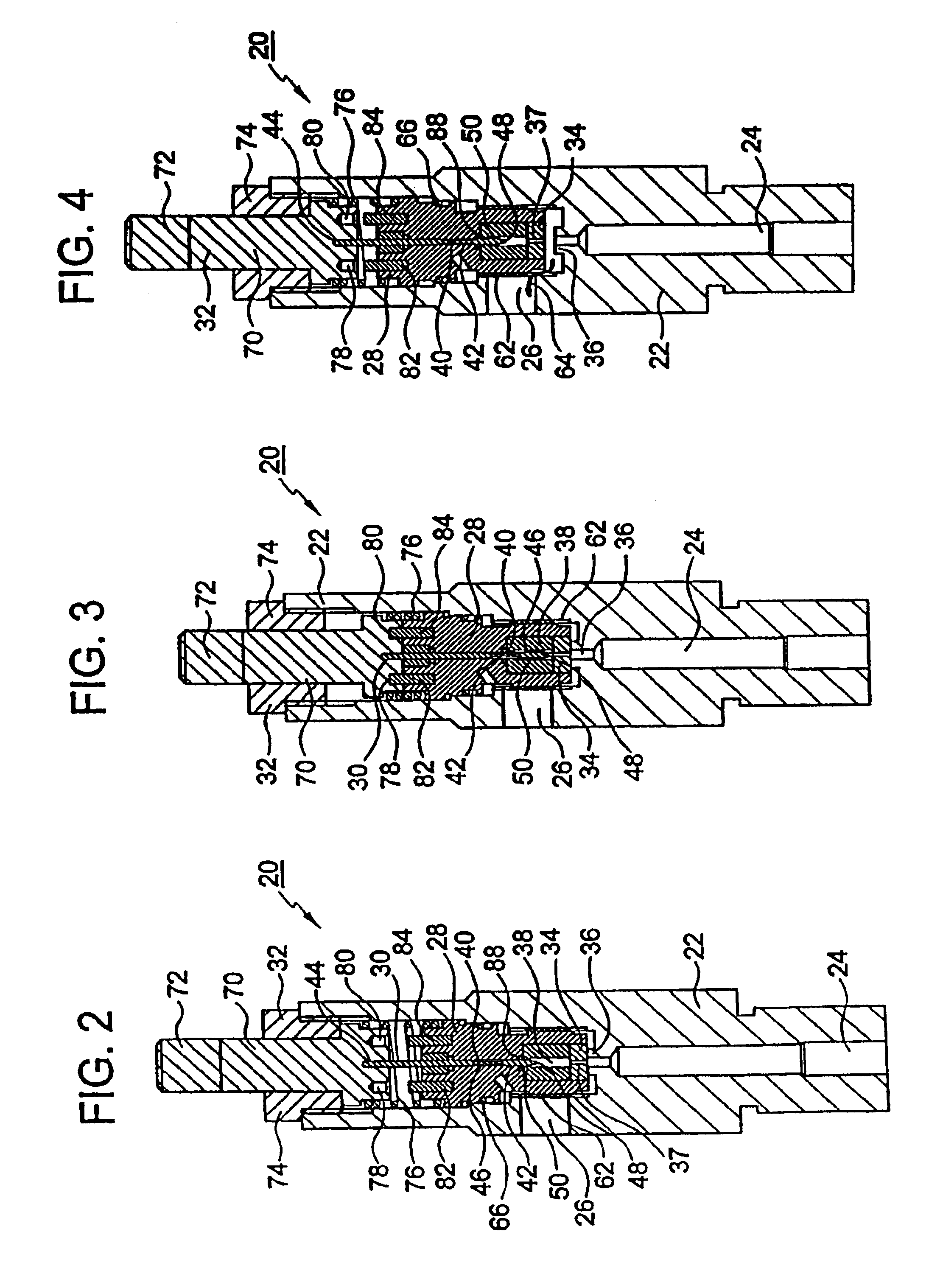
[0032]Referring now to FIG. 1, the oxygen supply system 10 includes a pressure regulator 12, a conduit 14 for flowing oxygen from the pressure regulator 12 to a patient (not illustrated), a source of oxygen 16, and a post valve 20 for preventing oxygen from flowing out of the source 16. The source 16 may be an oxygen cylinder, for example. As discussed in more detail below, the valve 20 may be arranged to prevent a high pressure surge from occurring in the pressure regulator 12 when the valve 20 is opened. In addition to oxygen, the present invention may be also used to handle ni...


PUM


Abstract

A surge prevention valve may be used to prevent the formation of an initial surge of high pressure. The valve may be located, for example, between a high pressure gas cylinder and a medical pressure regulator. The valve is provided with first and second valves located within a housing and integrating a pressurization orifice. The initial opening of the valve in an axial direction enables gas to flow through the pressurization orifice at a first flow rate. The full opening of the valve in the axial direction enables the gas to flow through the second valve at a second flow rate, which is much higher than the first flow rate. The controlled pressurization of the gas through the orifice delays the time during which the gas reaches full recompression.

Description

[0001]This is a continuation-in-part of U.S. patent application Ser. No. 09 / 374,130, filed Aug. 9, 1999, the entire disclosure of which is incorporated by reference herein.BACKGROUND OF THE INVENTION[0002]The present invention relates generally to a device for handling a gas, such as oxygen and nitrous oxide, under high pressure. The present invention also relates to a valve for controlling the flow of gas and to a system for reducing or preventing high pressure surge.[0003]Known high pressure oxygen delivery systems are provided with an oxygen cylinder, a cylinder valve and a pressure regulator. The oxygen cylinder may be charged with pure oxygen at a pressure of two thousand two hundred pounds per square inch (psi) or more in the United States and over three thousand psi in other countries. The valve is attached to the cylinder to stop the flow of oxygen to the regulator. The pressure regulator is designed to reduce the tank pressure to under two hundred psi. Most pressure regulat...

Claims


Application Information

Patent Timeline
Patent Type & Authority Patents(United States)
IPC IPC(8): F16K1/00F17C13/04F16K1/30F16K1/32F16K1/52F16K1/02F16K47/04
CPCF16K1/305F17C13/04F16K1/302F16K1/303F16K1/306F16K1/307F16K1/526F16K1/54F16K1/52F17C2270/025Y10S137/908F17C2201/0109F17C2201/032F17C2201/058F17C2205/0329F17C2205/0338F17C2205/0385F17C2205/0394F17C2221/011F17C2223/0123F17C2223/036F17C2250/0626F17C2260/021F17C2265/012Y10T137/7782Y10T137/88046Y10T137/87056Y10T137/8803Y10T137/86976Y10T137/7833Y10T137/86944Y10T137/0318Y10T137/87096Y10T137/87088Y10T137/88022Y10T137/87008Y10T137/7832Y10T137/8704Y10T137/88038
Inventor KROUPA, KEVIN D.KULLMANN, WILLIAM J.MURPHY, IAN F.
Owner ALLIED HEALTHCARE PROD INC
Why Eureka
Try Eureka