Bilge water reclamation system and process

a technology of bilge water and reclamation system, applied in the direction of water/sewage treatment by ion exchange, water/treatment water by electric/magnetic means, etc., can solve the problems of not reaching the level of success and adversely affecting the plankton population, so as to reduce the load of activated carbon, facilitate the electrocoagulation process, and reduce the effect of contaminants

Inactive Publication Date: 2005-06-07
TIPTON GARY A
View PDF11 Cites 68 Cited by
  • Summary
  • Abstract
  • Description
  • Claims
  • Application Information

AI Technical Summary

Benefits of technology

[0018]Ozone is injected at two points in the process. A small amount of ozone is injected prior to the electrocoagulation process. Some organics affect the electrocoagulation process. Injection of ozone reduces these contaminants and facilitates the electrocoagulation process. Ozone is also injected prior to the activated carbon. The ozone oxidizes the organics present in the wastewater. This reduces the load on the activated carbon. Water in the clean water-holding tank is circulated continuously through the activated carbon and the ozone injection zone. As the organics are reduced, the ozone will react with the organics captured by the activated carbon. This will purge the activated carbon extending the life of the activated carbon.

Problems solved by technology

One of the largest contributors to contamination of the world's beaches is the dumping of bilge water at sea.
A very small amount of hydrocarbons dissolved in seawater will adversely affect plankton population.
Prior art methods have met with some success, however, they do not achieve the level of success of the system of current invention, which includes, among other things, injection of ozone prior to an electrocoagulation processing and re-circulation of the treated wastewater to re-charge an activated hydrocarbon filter.

Method used


Image

  • Bilge water reclamation system and process
  • Bilge water reclamation system and process

Examples


Embodiment Construction

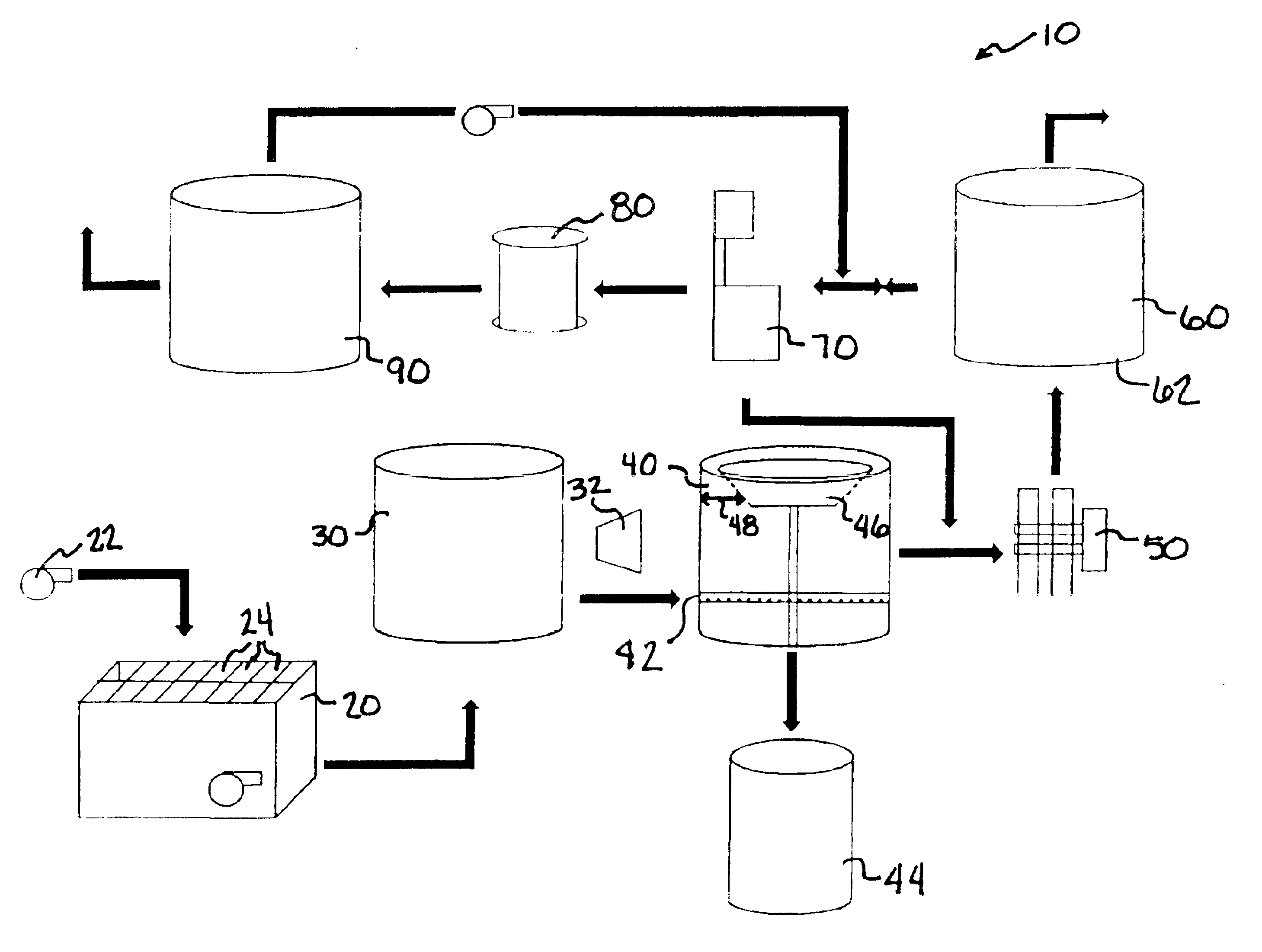
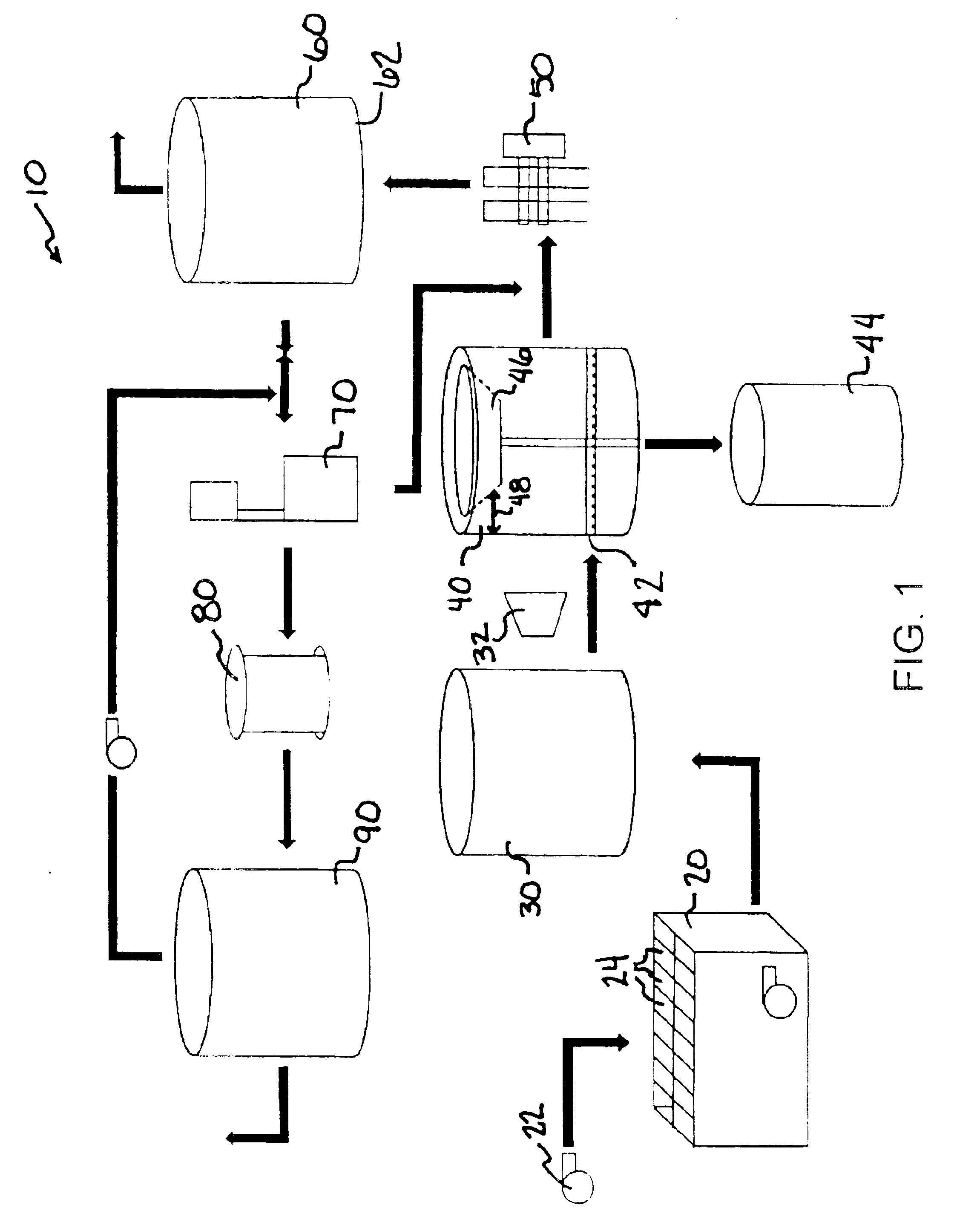
[0021]FIG. 1 depicts the inventive bilge water treatment system 10. The bilge water treatment system 10 comprises a sump 20, a holding tank 30, an oil / water separator 40, at least one electrocoagulation cell 50, a separation / retention tank 60, an ozone generator 70, a carbon filter 80, and a discharge tank 90. The process for treating bilge water includes receiving wastewater influent, separating oil from the wastewater, injecting ozone into the wastewater, using electrocoagulation to treat the wastewater, retaining the waste water to separate any flocculant and agglomeration, injecting more ozone into the waste water, filtering the waste water through activated carbon, treating sludge and discharging clean water.

[0022]Wastewater influent. A few of the most important factors to consider in receiving the wastewater such as bilge and ballast water is to reduce the time required to offload, to accept a variety of delivery methods, and to protect against spillage or environmental contam...


PUM

PropertyMeasurementUnit
sizeaaaaaaaaaa
velocityaaaaaaaaaa
voltageaaaaaaaaaa

Abstract

A system and method for treating and removing hydrocarbon and other contaminants in bilge and ballast water, utilizing a multiple progressive process that chemically and electrically treats-and removes contaminants. Wastewater, received by a sump, is transmitted to a holding tank and treated, over a period of time while-influent wastewater continues off loading. The wastewater is pumped to an oil / water separator tank that decants free-floating oil from the wastewater to an oil retention tank. The wastewater then undergoes an electrocoagulation process where emulsions are broken and compounds that further aid treatment are created. The treated water flows to a retention / separation tank where contaminant particles coalesce and separate. Water is decanted and transferred to a clean water holding tank through an ozone injection system and an activated carbon filter. Treated water is recirculated until it exits the system meeting discharge limits for organics and metals allowing release into the environment.

Description

CROSS-REFERENCE TO RELATED APPLICATIONS[0001]This application claims the benefit of the filing date of U.S. Provisional Patent application No. 60 / 414,810 filed in the United States Patent and Trademark Office on Sep. 30, 2002.STATEMENT REGARDING FEDERALLY SPONSORED RESEARCH OR DEVELOPMENT[0002]Not Applicable.BACKGROUND OF THE INVENTION[0003]1. Field of the Invention[0004]This invention relates to a process to treat a fluid column by removing organics, metals and other non-organic contaminants, and provides discharge within regulatory and environmental limits. The invention includes design of an improved electrical treatment process, a process flow allowing rapid and economical treatment of a contaminated fluid column. The invention also includes a process for regenerating activated carbon as an active unit of the treatment process.[0005]2. Description of the Related Art[0006]Processes to treat water contaminated with dissolved and suspended organic materials have existed for many ye...

Claims


Application Information

Patent Timeline
Patent Type & Authority Patents(United States)
IPC IPC(8): C02F9/00B63B17/00C02F1/463C02F1/78C02F1/28C02F1/40
CPCB63J4/002C02F9/00B63J4/004C02F2103/008C02F2101/32C02F2101/301C02F1/78C02F1/283C02F1/40C02F1/463C02F1/52
Inventor TIPTON, GARY A.
Owner TIPTON GARY A
Why Eureka
Try Eureka