
Intellectual property protection in a programmable logic device

Inactive Publication Date: 2005-06-07
XILINX INC
View PDF12 Cites 177 Cited by
  • Summary
  • Abstract
  • Description
  • Claims
  • Application Information

AI Technical Summary

Benefits of technology

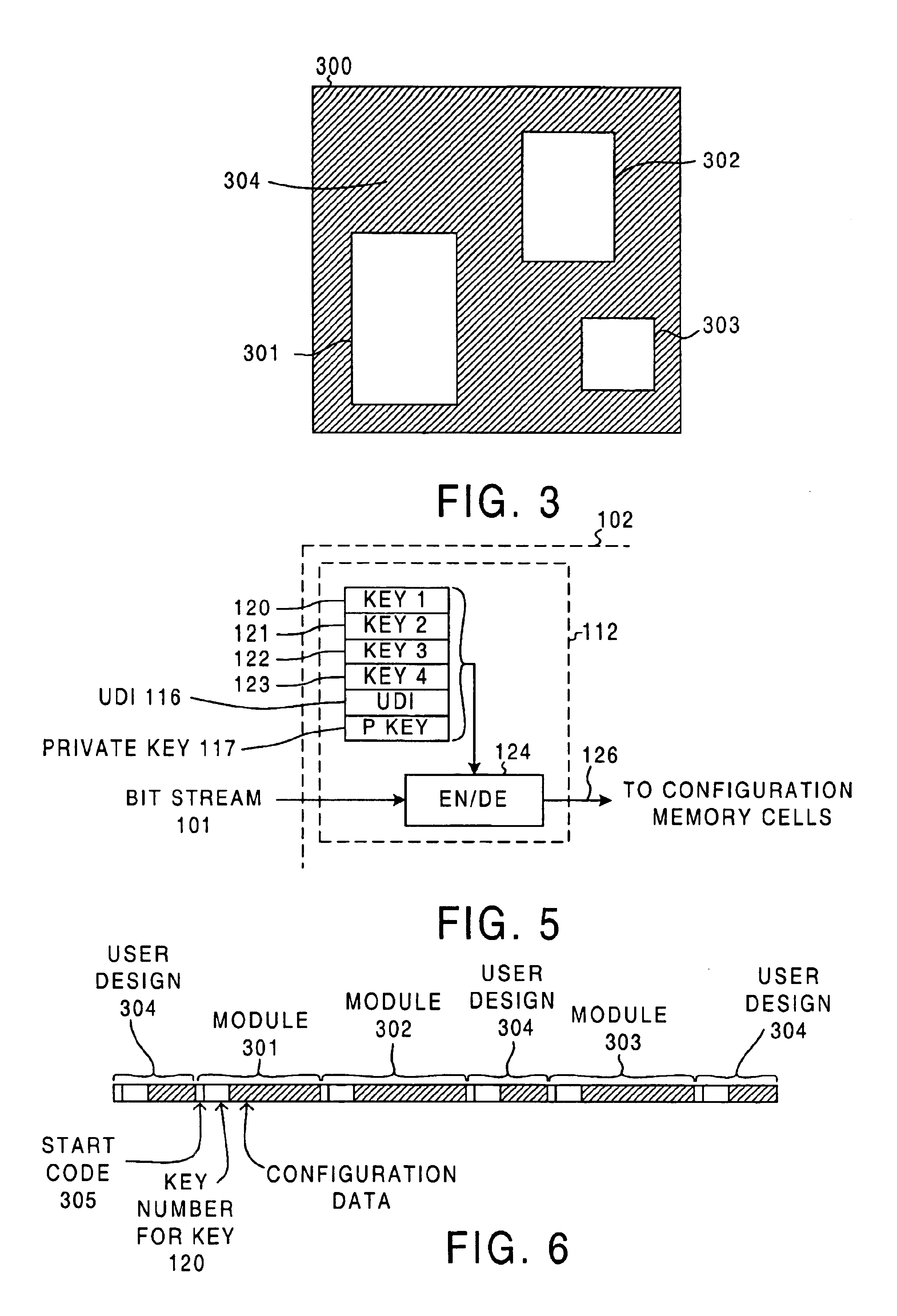
[0018]Not only are IP module keys for IP modules encrypted and sent to the target PLD, but a “user key” for the portion of the user-specific design contributed by the user is also encrypted and sent to the target PLD. No authorization code is required for the encryption of the user key and the passing of this user key to the PLD. The use of this user key to decrypt the appropriate portion of the bitstream occurs as described above in connection with the IP module keys. In this way, the user-specific design of a first user is protected from copying by a second user because the portion of the user-specific circuit designed by the first user is encrypted with a user key not known to the second user. The IP modules of the IP vendors are secure from copying by a user because the IP module portions of the bitstream are encrypted with IP module keys not known to the user.

Problems solved by technology

Without knowledge of the protocol and the significance of the individual bits of the bitstream, another user cannot readily regenerate the actual circuit by inspection of the bitstream.
Over recent years, such user-specific circuits have typically increased in size and complexity.
Simultaneously, market forces have reduced the amount of time practically available for developing such large user-specific circuits.
A problem, however, exists in that the user's user-specific design can be copied.
Without the key, the copier would have a difficult time recovering the bitstream.
Not only is one user's copying of another user's design a problem, but the unauthorized reincorporation of a vendor-supplied IP module into other user designs is also a problem.
If the number read from the computer is not appropriate for the authorization number provided by the user, then the user-verification process fails and the permission verification system does not allow the IP module to be decrypted.
Moreover, the design processing system will not include configuration data for the IP module in the output programming file.
In this scheme, however, the configuration data so generated is output from the design processing system in unencrypted form.
An authorized but nonetheless unscrupulous user could copy the programming file of bitstream information or a portion thereof and reuse it in an unauthorized fashion outside the control of the design processing system.

Method used


Image

  • Intellectual property protection in a programmable logic device
  • Intellectual property protection in a programmable logic device
  • Intellectual property protection in a programmable logic device

Examples


Embodiment Construction

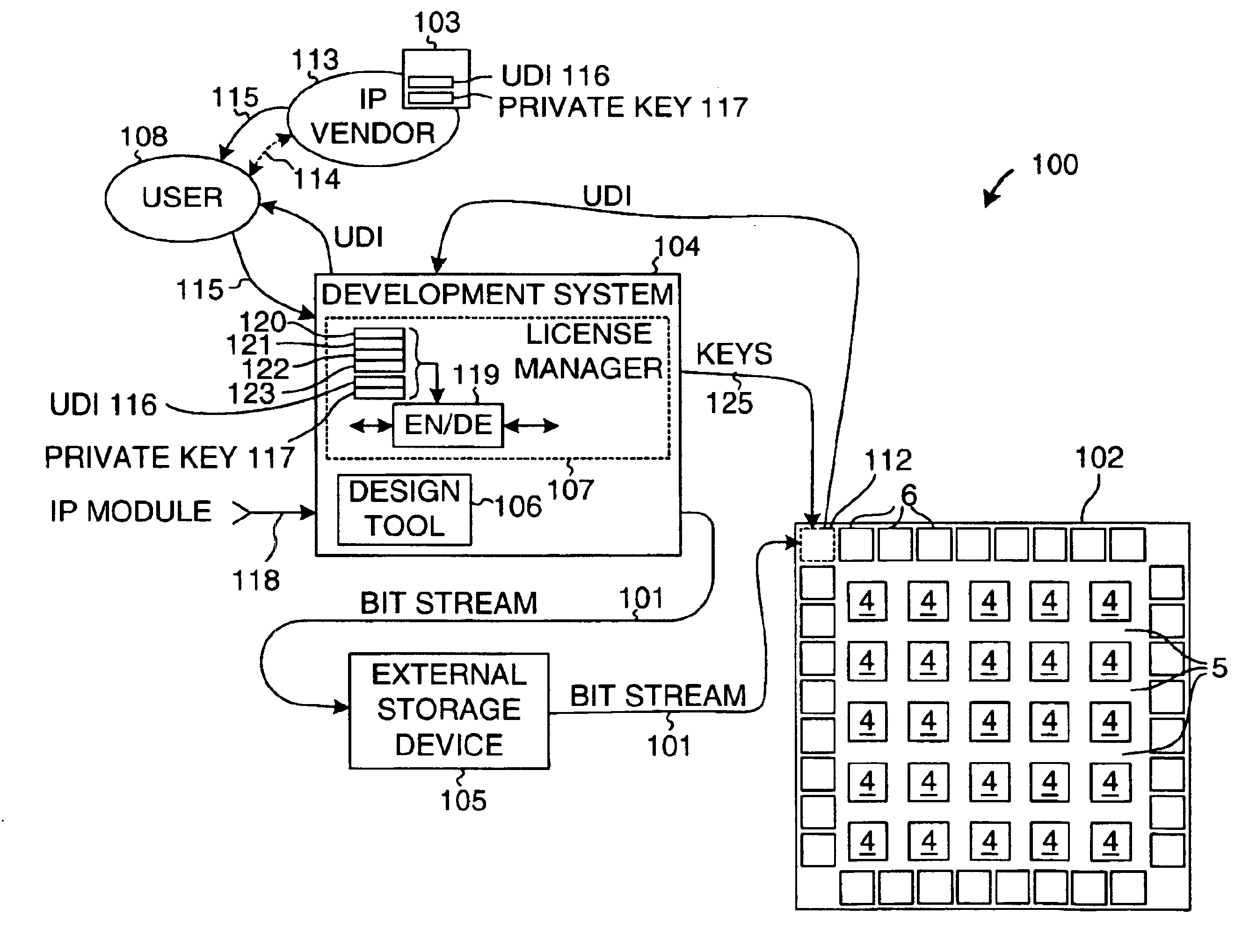
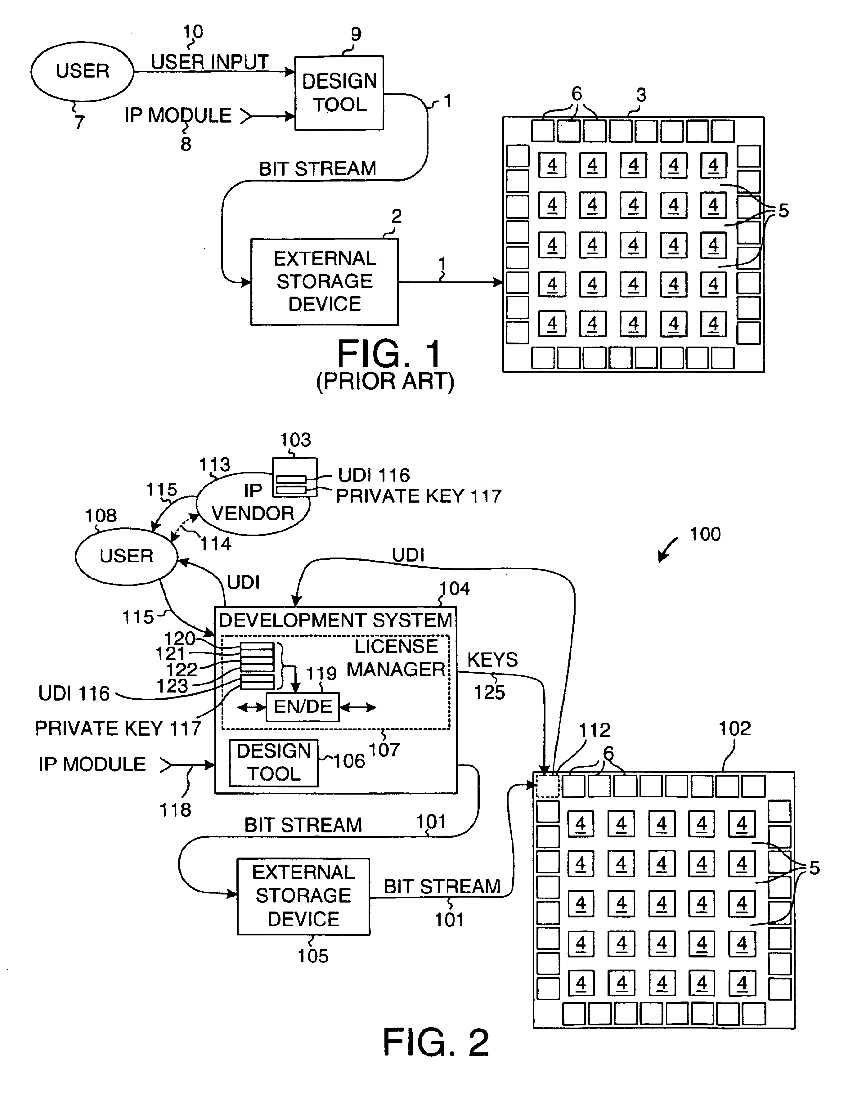
[0028]FIG. 2 is a simplified diagram illustrating a system 100 that carries out a method in accordance with an embodiment of the present invention. A configuration bitstream 101 for a user-specific circuit is loaded into a target FPGA integrated circuit 102 in such a way that vendor-supplied IP module design information in the bitstream 101 is protected from unauthorized use. System 100 includes authorization code generating software 103, a development system 104, an external storage device 105, and target FPGA 102. The development system 104 typically involves software executing on a personal computer or a workstation and includes a capture / design tool 106 and a license manager 107. A user 108 uses the capture / design tool 106 to design the user-specific circuit, to simulate it, to map, place and route it on FPGA 102, and to generate the configuration bitstream 101 for configuring FPGA 102. For additional information on an exemplary development system, see: pages 2-1 through 2-11 of...


PUM


Abstract

Individual IP vendors can directly license their IP modules to PLD users. Each PLD has a unique device identifier (UDI). If a user obtains a license to use an IP module on a particular PLD, then the IP vendor issues the user an authorization code (AC). The user supplies the AC to a license manager. The license manager decrypts the AC and checks that the UDI of the supplied AC matches the UDI of the PLD. If the two match, then the license manager encrypts a key, and sends the encrypted key to the PLD. The PLD uses a private key to decrypt the key. When the configuration bitstream for the design is later sent to the PLD, the license manager encrypts the IP module portion of the bitstream with the key. The PLD receives the bitstream and uses the decrypted key to decrypt the IP module portion.

Description

TECHNICAL FIELD[0001]This invention relates to a method and apparatus for securing configuration data used to configure a programmable logic device.BACKGROUND INFORMATION[0002]The term Programmable Logic Device (PLD) designates a class of devices that are programmable by end users to realize user-specific circuits. Examples of PLDs are FPGAs (Field Programmable Gate Arrays) and EPLDs (Erasable Programmable Logic Devices). To use a PLD, a user captures a circuit design using any of several capture / design tools. The user then uses the capture / design tool to convert the captured design into device-specific configuration data. The configuration data is commonly stored in an external storage device, such as an EPROM. Upon startup, the storage device supplies the configuration data to the PLD, thereby configuring the PLD to realize the user-specific circuit. Since the configuration data is often supplied in serial fashion, the configuration data is called a “bitstream”. The PLD, having re...

Claims


Application Information

Patent Timeline
IPC IPC(8): H04L9/32G06F21/00
CPCG06F21/76H04L9/0825H04L9/0894H04L9/0866H04L2209/603
Inventor PARLOUR, DAVID B.BALLANTYNE, RICHARD S.
Owner XILINX INC
Learn More