Method for adjusting coolant temperature in an internal combustion engine

a technology for internal combustion engines and coolants, which is applied in the direction of engine cooling apparatus, engine controllers, electric control, etc., can solve the problem of light additional energy consumption

Inactive Publication Date: 2005-06-14
CONTINENTAL AUTOMOTIVE GMBH
View PDF1 Cites 25 Cited by
  • Summary
  • Abstract
  • Description
  • Claims
  • Application Information

AI Technical Summary

Benefits of technology

[0005]The invention discloses a method for controlling the coolant temperature of the generic system descri

Problems solved by technology

Increasing the rotational speed of the pump for a short

Method used


Image

  • Method for adjusting coolant temperature in an internal combustion engine
  • Method for adjusting coolant temperature in an internal combustion engine
  • Method for adjusting coolant temperature in an internal combustion engine

Examples


Embodiment Construction

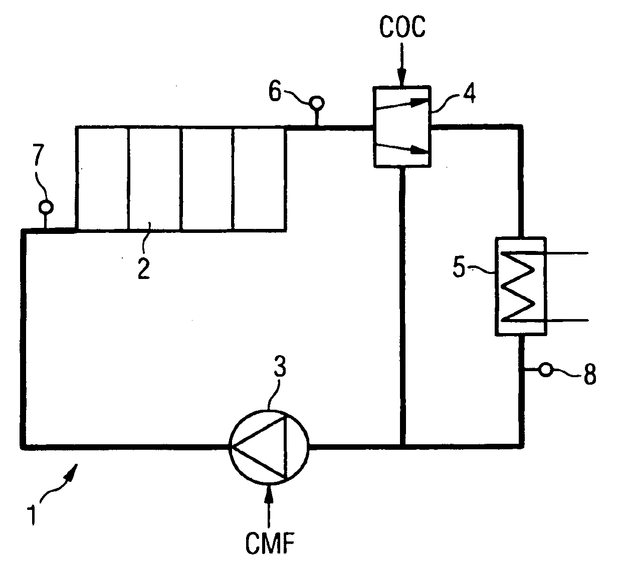
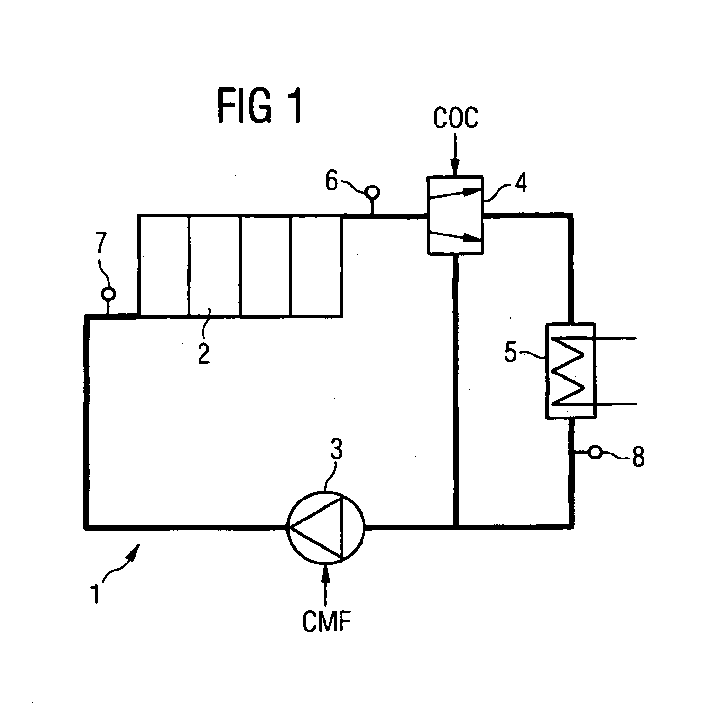
[0014]FIG. 1 is a schematic representation of the coolant circuit 1 of an internal combustion engine 2. The coolant circuit 1 includes a coolant pump 3 and a bypass valve 4. The coolant pump 3 is an electrically driven pump, for example, a radial pump of which the rotational speed can be controlled. The bypass valve 4 that routes the coolant flow coming from the internal combustion engine 2, depending on its position, through the radiator 5 or passing radiator 5 to the coolant pump 3 is a distributing valve whose position can be controlled electrically in which case, as a function of the setting of the bypass valve 4, a greater or lesser coolant flow is routed through the radiator 5.

[0015]FIG. 1 further shows temperature sensors 6, 7 and 8 by means of which the coolant temperature is detected at the outlet and inlet of the internal combustion engine 2 as well as at the outlet of the radiator 5. However, it should be pointed out that no separate temperature sensor is required for det...


PUM


Abstract

A method for adjusting coolant temperature in an internal combustion engine (2), whereby the coolant circuit thereof contains an electrically driven coolant pump (3) and an electrically controllable bypass valve (4). If the setpoint value of the coolant temperature changes in an abrupt manner, the rotating speed of the coolant pump (3) rises during the short interval in order to reduce the dead time required for adjustment. A Smith controller, which takes into account dead times of the system, is used to regulate the bypass valve.

Description

CLAIM FOR PRIORITY[0001]This application claims the benefit of priority to international application PCT / DE02 / 01574, which was filed on Apr. 30, 2002 and published in the German language on Nov. 21, 2002, which application claims benefit to German application DE 10123444.9, filed May 14, 2001.TECHNICAL FIELD OF THE INVENTION[0002]This invention relates to a method for controlling the coolant temperature in an internal combustion engine coolant circuit with an electrically driven coolant pump and an electrically controllable bypass valve which routes a variable part of the coolant flow through a bypass line containing a radiator.BACKGROUND OF THE INVENTION[0003]Instead of a conventional thermostat valve and a conventional coolant pump driven mechanically by the internal combustion engine, this method uses an electrically controlled bypass valve and an electrically driven coolant pump. In this case, the rotational speed of the coolant pump and the setting of the bypass valve are regul...

Claims


Application Information

Patent Timeline
IPC IPC(8): F01P7/16F01P7/14
CPCF01P7/164F01P7/167F01P2007/146F02D2041/1431F01P2023/08F01P2025/30F01P2025/32F01P2023/00
Inventor KILGER, MICHAEL
Owner CONTINENTAL AUTOMOTIVE GMBH
Why Eureka
Try Eureka