Fuel injection method in fuel injector

a fuel injection and fuel injector technology, applied in the direction of fuel injecting pumps, machines/engines, electric control, etc., can solve the problems of deteriorating air availability in cylinders, affecting the efficiency of fuel injection, and easy generation of smoke (black smoke) to achieve the effect of high degree of freedom

Inactive Publication Date: 2005-06-14
TOYOTA JIDOSHA KK
View PDF12 Cites 69 Cited by
  • Summary
  • Abstract
  • Description
  • Claims
  • Application Information

AI Technical Summary

Benefits of technology

[0057]In the fuel injection method of the tenth exemplary aspect, a fuel channel area of the cylinder is changed by the piston control valve, and a moving rate of the piston is changed. Namely, when a channel area of a fuel into the cylinder is changed by the piston control valve, an amount of a fuel flowing into/out of the cylinder is changed, and a moving rate of the piston is changed. An injection pattern of fuel injected from the fuel injection nozzle is controlled to an optimal value, and fuel injection is performed. Con...

Problems solved by technology

However, when an injection pressure by a conventional accumulator fuel injector (common rail injection system) uses a nozzle injection opening diameter which is smaller than an existing one, it is assumed that an injection period becomes too long at a high engine speed and at a high load region thereby hindering a high power of fuel injection.
For this reason, with the same injection pressure as before, during a high engine speed, spray is more likely to be run than during a low engine speed, air availability in a cylinder is deteriorated, and smokes (black smokes) are easily generated.
In consideration of rigidity of the fuel injector, there is a limit in ability of further increasing the existing injection pressure (in other words, it is difficult to make a conventional injection pressure extremely higher).
However, in this fuel injector, there have been drawbacks resulting in the following problems.
Such an excessively long injection period can be a cause to hinder high power, which is not preferable.
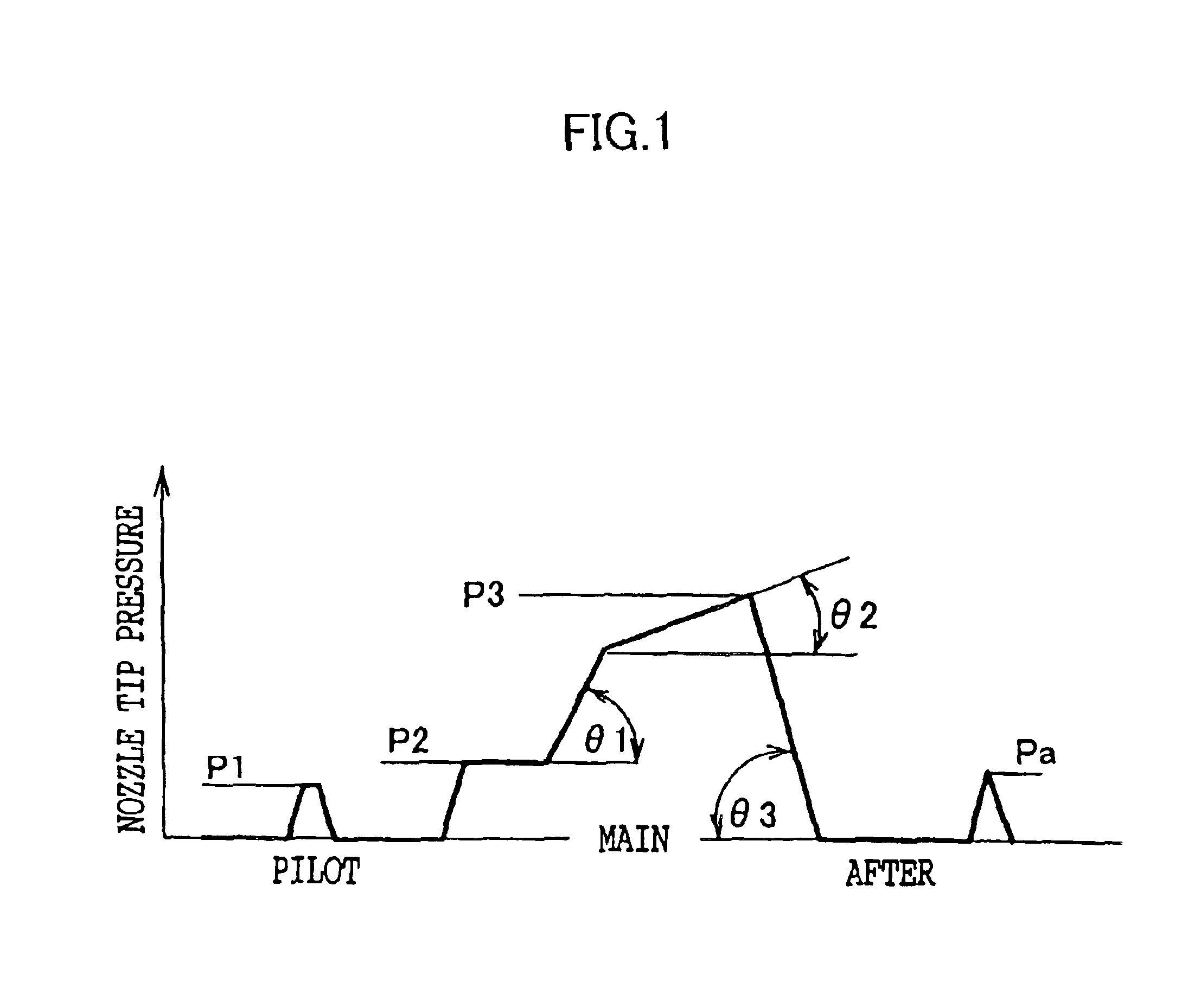
However, an optimal value of an injection pressure during the pilot injection is different from that of the main injection and generally lower than that of the main injection.
This is because, since fuel is injected considerably earlier than a compression top dead point, air temperature or density in a cylinder becomes low, and when a...

Method used


Image

  • Fuel injection method in fuel injector
  • Fuel injection method in fuel injector
  • Fuel injection method in fuel injector

Examples


example 1

[0217]FIG. 16 shows a schematic diagram of a method of setting an injection amount and an injection pressure by respectively controlling an opening timing of the needle valve 48 (an operational timing of the injection control valve 52) and an operational timing of the intensifier 54 (operational timing of the piston control valve 60) (by controlling an operational phase difference between valves).

[0218]Here, FIG. 16 shows diagrams of patterns of changes in “injection pressure and injection amount” exerted when the injection control valve 52 is operated during respective periods of “from A0 to B”, “from A1 to B”, “from A2 to B” and “from A3 to B” in a case in which the piston control valve 60 is operated during a period of from “A1 to B”. Further, in examples shown in FIG. 16, a case is illustrated when an injection pressure is intensified by operating the intensifier 54 until fuel injection is completed.

[0219]In this way, in the fuel injection method according to the present inventi...

example 2

[0221]FIG. 17 shows a schematic diagram of a method of setting an injection amount and an injection pressure by respectively controlling an opening timing of the needle valve 48 (an operational timing of the injection control valve 52) and an operational timing of the intensifier 54 (operational timing of the piston control valve 60) (by controlling an operational phase difference between valves).

[0222]Here, FIG. 17 shows diagrams of patterns of changes in “injection pressure and injection amount” exerted when the injection control valve 52 is operated during respective periods of “from A0 to B”, “from A1 to B”, “from A2 to B”, “from A3 to B” and “from A4 to B” in a case in which the piston control valve 60 is operated during respective periods of “from A1 to A3” and “from A1 to A4”. Further, FIG. 17 shows examples of a case when intensification of an injection pressure by using the intensifier 54 is suspended during the fuel injection.

[0223]In this way, in the fuel injection method...

example 3

[0225]FIGS. 18A and 18B, and FIGS. 19A and 19B respectively show a schematic diagram of a method of setting an injection amount and an injection pressure at a common rail pressure by the accumulator 32 without operating the intensifier 54.

[0226]As can be seen from FIGS. 18A and 18B, and FIGS. 19A and 19B, an injection amount and an injection pressure can be arbitrarily set by controlling a setting of a common rail pressure due to the accumulator 32 and an opening timing of the needle valve 48 (operational timing of the injection control valve 52).


PUM


Abstract

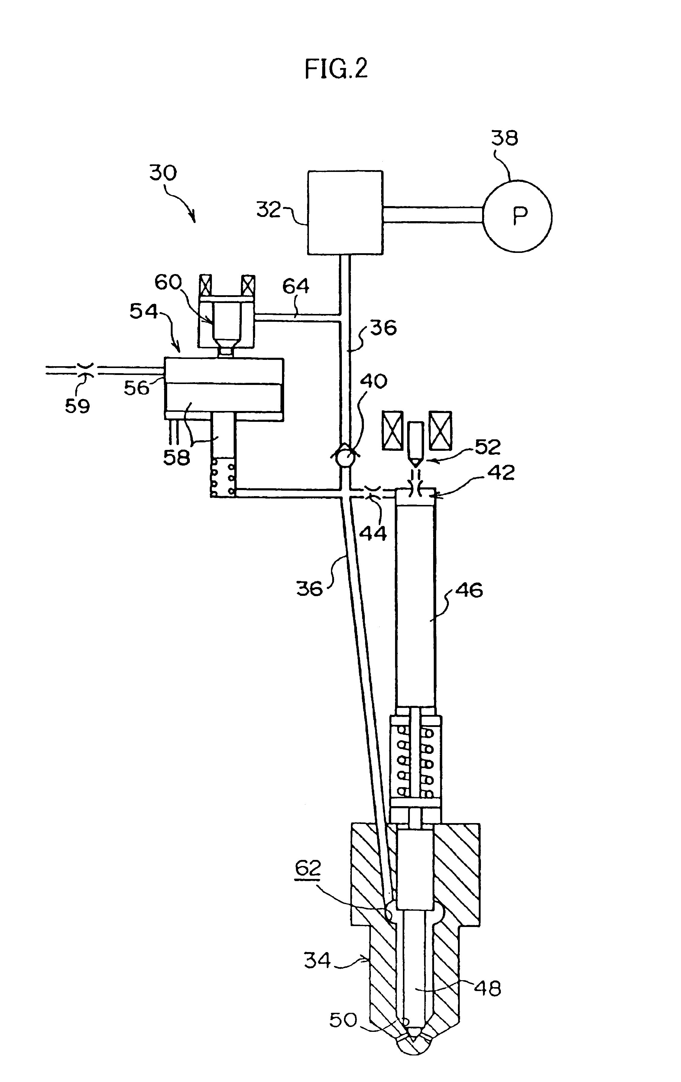
In fuel injector including an accumulator and an intensifier, fuel is injected such that an injection control valve and a piston control valve are individually controlled, an operational phase difference therebetween is regulated, and at least one of a maximum injection pressure, a rate of increase of an injection pressure at the start of an increase of pressure, a rate of decrease of the injection pressure at the completion of injection, a pilot injection pressure, and an after injection pressure of fuel injected from a fuel injection nozzle is arbitrarily changed. Namely, a pressure during a movement from a base common rail pressure of the accumulator to a static maximum pressure statically determined by an operation of the intensifier is positively used as a control factor of injection, whereby a fuel injection pattern can be implemented with an extremely high degree of freedom.

Description

FIELD OF THE INVENTION[0001]The present invention relates to a fuel injection method in a fuel injector for injecting a pressurized fuel oil from a fuel injection nozzle.BACKGROUND ART[0002]An accumulating type (common rail type) fuel injector is known in which a fuel pumped from a high pressure feed pump is accumulated by an accumulator (so-called “common rail”), and then injected from a fuel injection nozzle into an engine cylinder at a predetermined timing.[0003]In such an accumulator fuel injector, even when an engine speed is low, a predetermined fuel injection pressure can be maintained (the fuel injection pressure does not deteriorate). Accordingly, high pressure fuel injection contributes a great deal to an improvement of fuel consumption or high power of engine.[0004]However, it is known that the smaller the nozzle injection opening diameter of a fuel injector, the more effective for realizing an excellent emission (for cleaning up exhaust gas). However, when an injection p...

Claims


Application Information

Patent Timeline
IPC IPC(8): F02M59/36F02M59/00F02M59/20F02M59/10F02M45/08F02M47/02F02M45/04F02M45/06F02M45/00F02M63/02F02M63/00F02M47/00
CPCF02D41/3836F02D41/403F02D41/405F02M45/04F02M45/06F02M47/027F02M57/025F02M59/105F02M59/366F02M45/08Y02T10/44F02M63/0225Y02T10/40
Inventor HOTTA, YOSHIHIROWAKISAKA, YOSHIFUMIKAWAMURA, KIYOMINAKAKITA, KIYOMI
Owner TOYOTA JIDOSHA KK
Why Eureka
Try Eureka