Eureka AIR delivers breakthrough ideas for toughest innovation challenges, trusted by R&D personnel around the world.

Focusing arrangement and method in electro-optical readers

a technology of electro-optical readers and focusing arrangements, which is applied in the direction of camera focusing arrangements, printers, instruments, etc., can solve the problems of insufficient strength or rigidity of plates, difficult manufacturing, and large amount of lateral space needed to radially move plates into and out of optical paths

Inactive Publication Date: 2005-06-14
SYMBOL TECH LLC
View PDF6 Cites 4 Cited by
  • Summary
  • Abstract
  • Description
  • Claims
  • Application Information

AI Technical Summary

Benefits of technology

[0016]Another object of this invention is to provide an arrangement which is miniature, compact, lightweight, durable and power efficient in operation, and thus is ideally suited for portable hand-held applications.FEATURES OF THE INVENTION
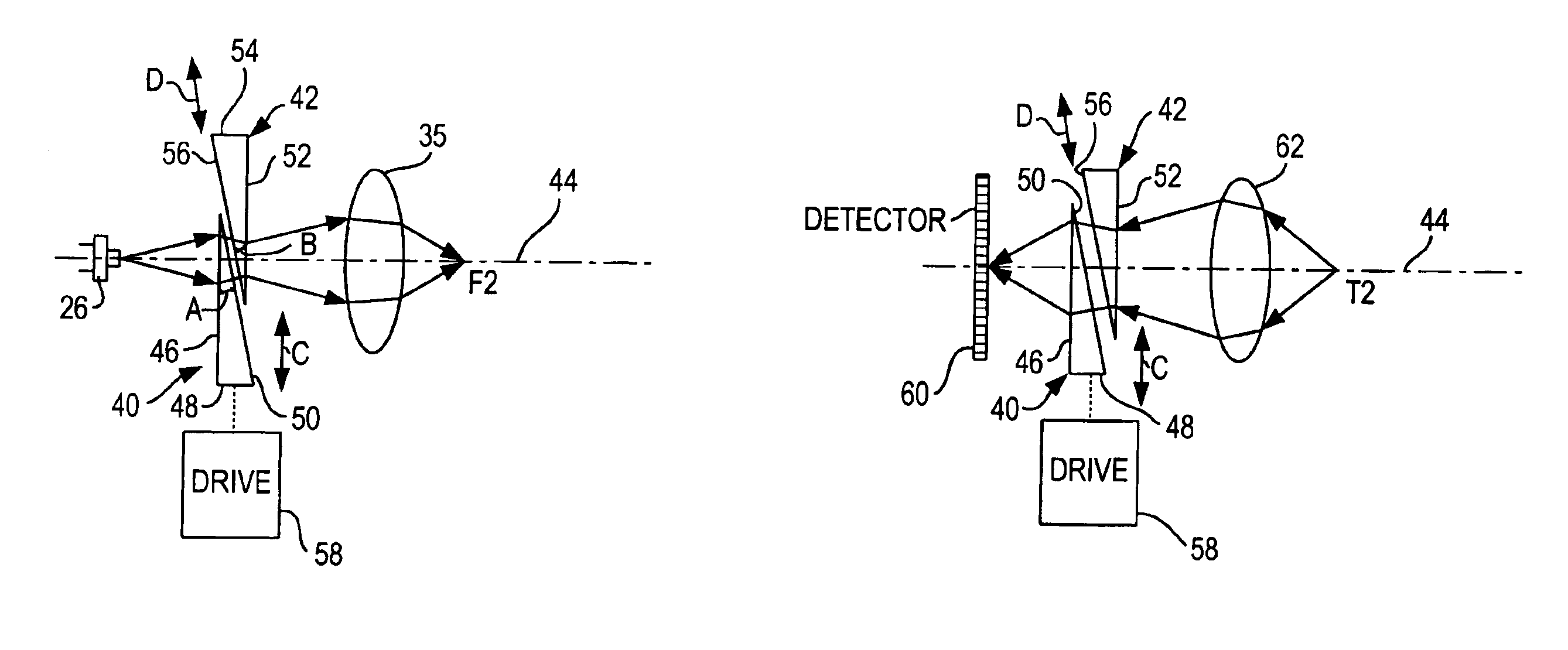
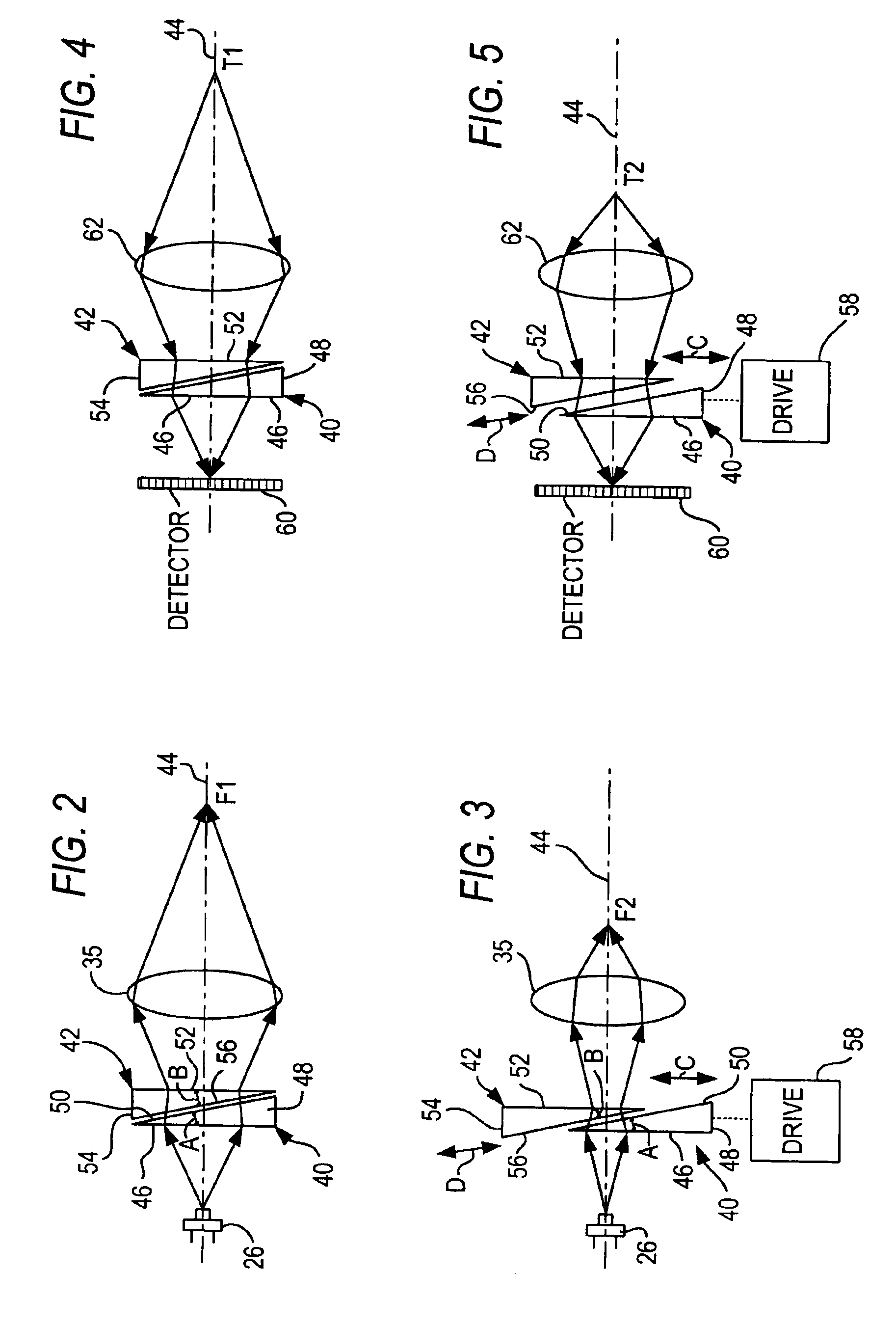
[0019]The required movement of one prism relative to the other is very small to achieve a usable wide range of focii. Using the previous example, in which the optical aperture is 3 mm in diameter and the required margin is 0.5 mm, one of the prisms of this invention need only be 4 mm in height, and the other only slightly larger in order to accommodate the required variation in focii. The movement can be in drive directions perpendicular to said at least one path, or along a common plane tilted relative to said at least one path. This minimal movement minimizes power consumption, vibration, noise, and overall size and weight of the arrangement and still achieves a practical range of focal distances.
[0020]The thinness of a plane parallel plate is no longer an issue. The prisms are readily manufactured with high optical quality and have sufficient thickness and strength to resist deformation in mounting and shock forces encountered during rough handling. A continuous focal change is achieved since the moving prism can be moved to an infinite number of positions.

Problems solved by technology

A very thin plate, however, whether made of glass or plastic, on the order of 0.5 mm in some applications, is difficult to manufacture while still maintaining acceptable optical quality.
The strength or rigidity of the plate is insufficient for applications requiring a high resistance to shock forces during expected rough handling.
In addition, the amount of lateral space necessary to radially move the plate into and out of the optical path is relatively large.

Method used


Image

  • Focusing arrangement and method in electro-optical readers
  • Focusing arrangement and method in electro-optical readers
  • Focusing arrangement and method in electro-optical readers

Examples


Embodiment Construction

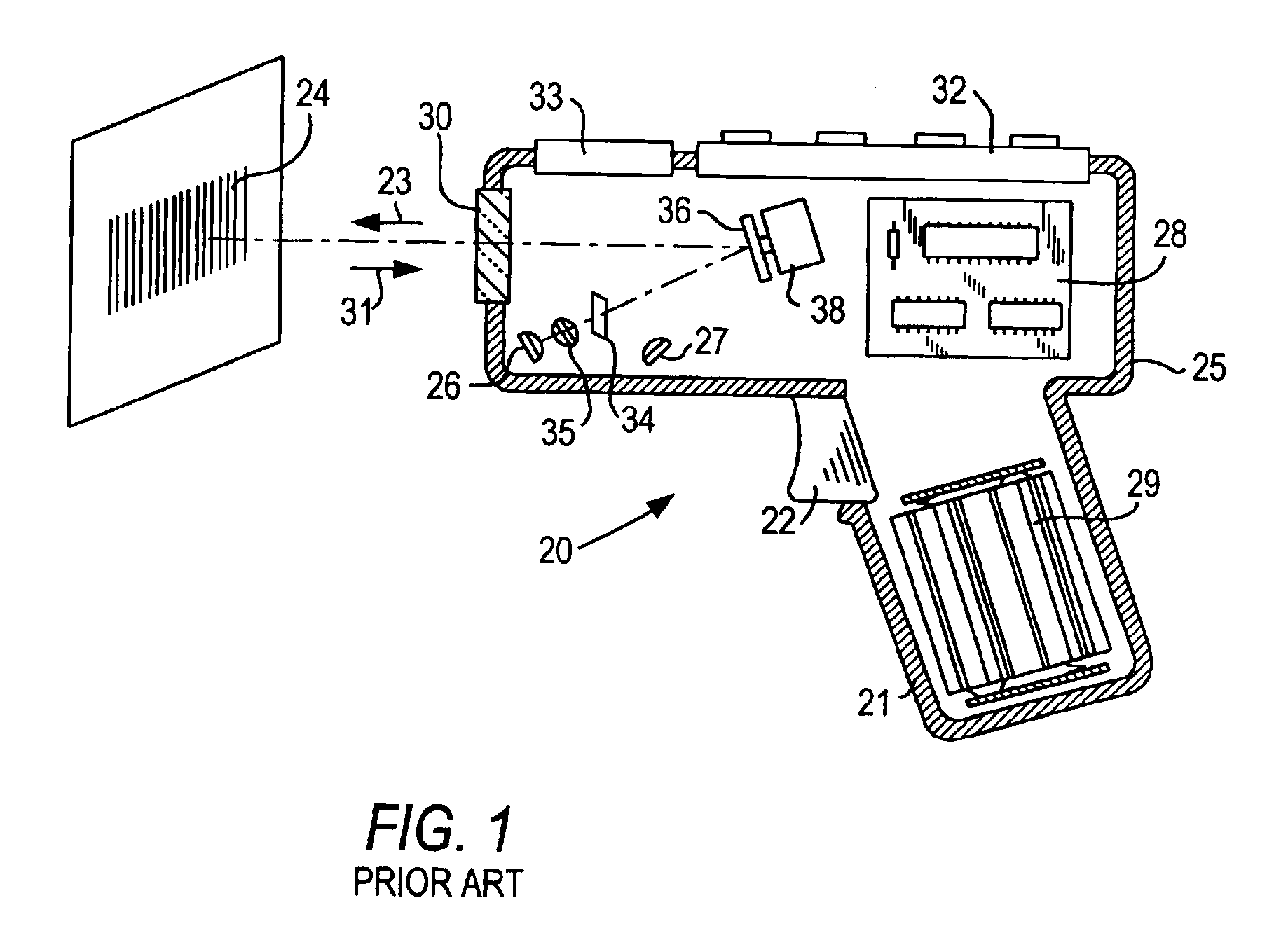
[0025]Reference numeral 20 in FIG. 1 generally identifies a hand-held reader for electro-optically reading indicia, such as bar code symbol 24, located in a range of working distances therefrom. The reader 20 has a pistol grip handle 21 and a manually actuatable trigger 22 which, when depressed, enables a light beam 23 to be directed at the symbol 24. The reader 20 includes a housing 25 in which a light source 26, a light detector 27, signal processing circuitry 28, and a battery pack 29 are accommodated. A light-transmissive window 30 at a front of the housing enables the light beam 23 to exit the housing, and allows return light 31 scattered off the symbol to enter the housing. A keyboard 32 and a display 33 may advantageously be provided on a top wall of the housing for ready access thereto.

[0026]In use, an operator holding the handle 21 aims the housing at the symbol and depresses the trigger. The light source 26 emits a light beam which is optically modified and focused by opti...


PUM


Abstract

Focusing in an electro-optical reader for reading indicia is obtained by moving one prism relative to another prism. An outgoing laser beam directed to indicia for reflection therefrom and / or return light reflected from the indicia is focused by the moving prism.

Description

BACKGROUND OF THE INVENTION[0001]1. Field of the Invention[0002]The present invention generally relates to electro-optical systems for reading indicia, for example, bar code symbols, having parts with different light reflectivities and, in particular, to an arrangement for, and a method of, focusing a light beam directed to the indicia, or focusing return light reflected from the indicia, by performing relative motion between a pair of prisms through which the light beam or the return light is transmitted.[0003]2. Description of the Related Art[0004]Various electro-optical readers and systems have previously been developed for reading bar code symbols appearing on a label, or on a surface of a target. The bar code symbol itself is a coded pattern of indicia. Generally, the readers electro-optically transform graphic indicia of the symbols into electrical signals which are decoded into alphanumeric characters. The resulting characters describe the target and / or some characteristic of...

Claims


Application Information

Patent Timeline
Patent Type & Authority Patents(United States)
IPC IPC(8): G03B3/10G06K7/10G06K7/14
CPCG02B2207/117G06K7/10811
Inventor HE, DUANFENG
Owner SYMBOL TECH LLC
Why Eureka
Eureka Blog
Learn More