Structure and method for an isolated boost converter

a boost converter and boost converter technology, applied in the direction of electric variable regulation, process and machine control, instruments, etc., can solve the problems of increased voltage stress on the primary switch, ringing between the parasitic leakage inductance, etc., and achieve the effect of substantially reducing the current stress on the secondary side components

Inactive Publication Date: 2005-06-14
DELTA ELECTRONICS INC
View PDF6 Cites 36 Cited by
  • Summary
  • Abstract
  • Description
  • Claims
  • Application Information

AI Technical Summary

Benefits of technology

[0010]According to a second embodiment of the present invention, an isolated boost converter includes three primary switches, two of which are simultaneously closed and opened, while the third switch is closed and opened before the opening and closing of the other two primary switches. Under this arrangement, the current stress on the secondary side components is substantially reduced because energy is transferred from the input to the output for a longer time than the first embodiment that has only the two primary switches. Specifically, in this second embodiment, the input-to-output energy transfer takes place when the third switch is closed, as well as during the subsequent period when the other two primary switches are closed.

Problems solved by technology

In either isolated boost converters, however, an increased voltage stress on the primary switches results from ringing between the parasitic leakage inductance of the transformer and the output capacitance of the primary switch (i.e., primary switch 102a or 102b) that is being turned off.

Method used


Image

  • Structure and method for an isolated boost converter
  • Structure and method for an isolated boost converter
  • Structure and method for an isolated boost converter

Examples


Embodiment Construction

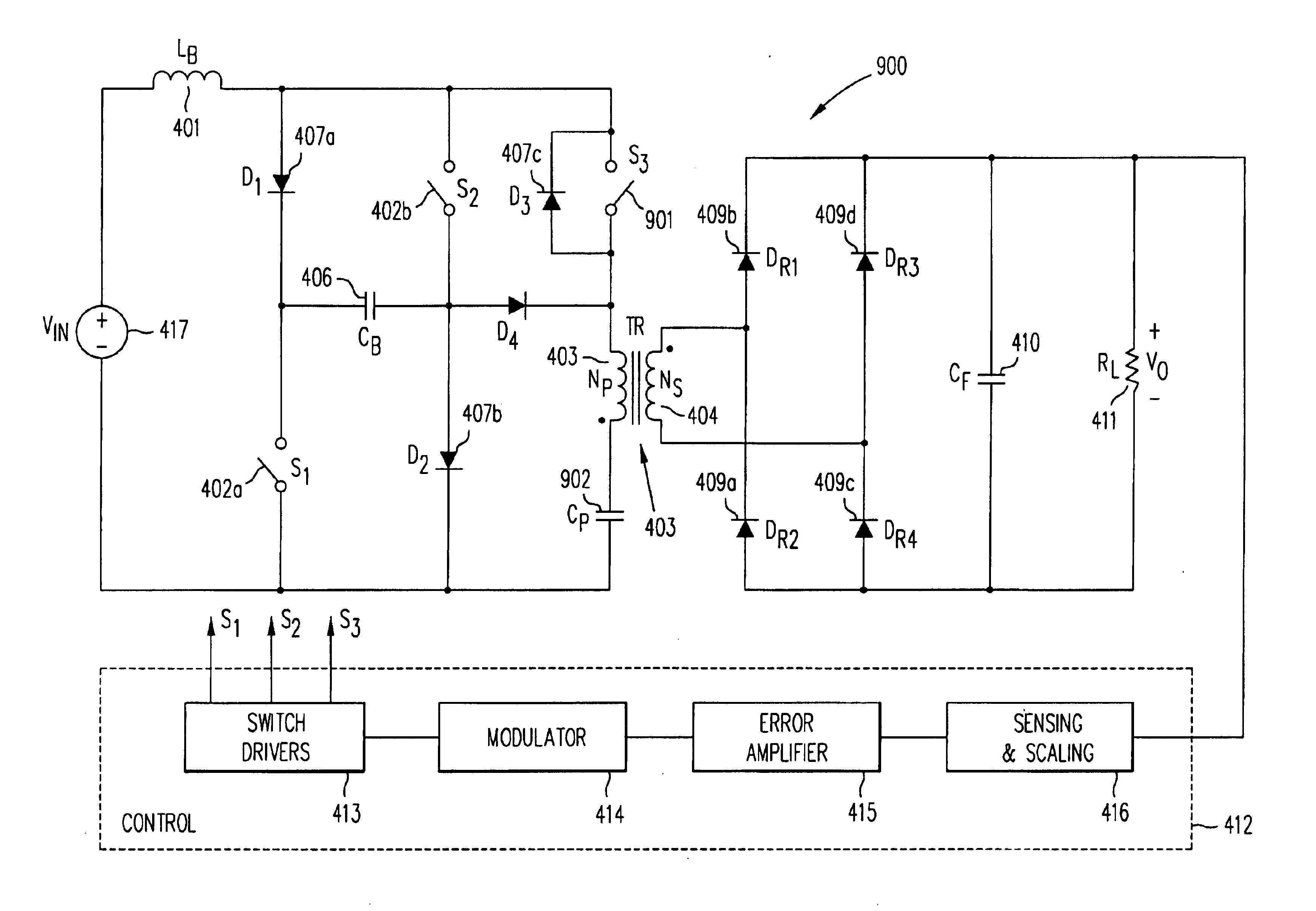
[0032]FIG. 4 shows a first embodiment of the present invention in isolated boost converter 400. As shown in FIG. 4, on the input side, isolated boost converter 400 includes voltage source 417 at voltage VIN, boost inductor 401 with an inductance value LB, switches 402a and 402b (controlled respectively by signals S1 and S2), primary-side energy-storage capacitor 406 with a capacitance value CB, rectifiers 407a, 407b and 407c (D1 through D3), and primary winding 404 of transformer 403 (TR). On the output side, isolated boost converter 400 includes the secondary winding 405 of transformer 403, which is connected to the full-bridge rectifier 408 implemented with rectifiers 409a-409d (DR1 through DR4), and filter capacitor 410 with capacitance value CF connected across load 411 (resistance value RL).

[0033]To illustrate the operation of isolated boost converter 400, FIG. 5 provides simplified circuit model 500 of isolated boost converter 400 of FIG. 4. In simplified circuit model 500, en...


PUM


Abstract

An isolated boost converter includes first and second switches that are switched simultaneously, a transformer and an energy storage capacitor on the primary side of the transformer for storing energy received from input power source. In one embodiment, when the first and second switches are closed, the energy in the capacitor is transferred to the output load while a boost inductor is charged, and when the first and second switches are open, the boost inductor provides energy from the input voltage source to supply the load and to charge the capacitor, In one embodiment, a third switch is provided to relieve the voltage stress on the secondary side.

Description

BACKGROUND OF THE INVENTION[0001]1. Field of the Invention[0002]The present invention relates to power converters (e.g., boost converters). In particular, the present invention relates to isolated power converters, such as boost converters.[0003]2. Discussion of the Related Art[0004]Boost converter topologies have been extensively used in various AC / DC and DC / DC power conversion applications. In fact, virtually all the front ends of today's AC / DC power supplies that include a power-factor correction (PFC) feature are implemented using a boost converter topology. Boost converter topologies are also used in numerous applications where a relatively low battery-powered input voltage is used to generate a high output voltage. The vast majority of conventional power converters that use a boost topology are non-isolated. However, in some applications, boost converters with galvanically-isolated input and output are required.[0005]Isolated boost converter having one or more isolation transf...

Claims


Application Information

Patent Timeline
Patent Type & Authority Patents(United States)
IPC IPC(8): H02M3/335H02M3/24H02M1/34H02M3/337
CPCH02M1/34H02M3/3376Y02B70/1491H02M2001/346H02M2001/342H02M1/342H02M1/346Y02B70/10
Inventor JANG, YUNGTAEKJOVANOVIC, MILAN M.
Owner DELTA ELECTRONICS INC
Why Eureka
Try Eureka