Router apparatus and frame transfer method

a frame transfer and frame technology, applied in the field of routers, can solve the problems of increasing the processing load within the router, increasing the processing time required for transferring the received datalink layer frame,

Inactive Publication Date: 2005-06-14
KK TOSHIBA
View PDF5 Cites 5 Cited by
  • Summary
  • Abstract
  • Description
  • Claims
  • Application Information

AI Technical Summary

Benefits of technology

[0013]It is therefore an object of the present invention to provide a mechanism for enabling a router that connects shared-media networks, such as the Ethernet, to do

Problems solved by technology

During the above transfer operation, a heavy load of processing is imposed on the router, such as conversion from the received datalink layer frame into a network layer packet, search through the network layer routing table, and re-conversion from the packet into a datalink frame, thereby increasing the processing time required for

Method used


Image

  • Router apparatus and frame transfer method
  • Router apparatus and frame transfer method
  • Router apparatus and frame transfer method

Examples


Embodiment Construction

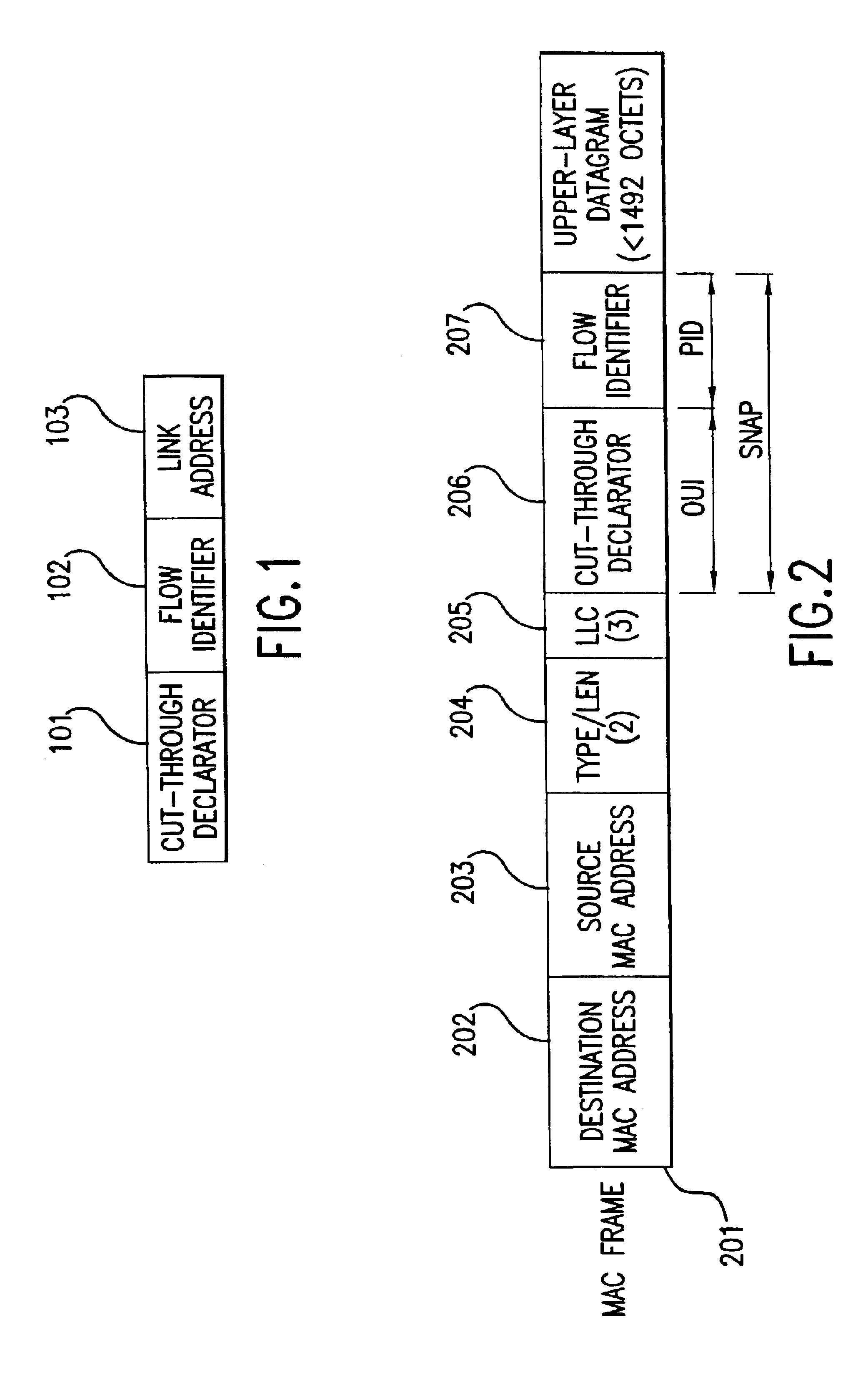
[0067]FIG. 1 illustrates an example of the format of a cut-through label identifier used in achieving the cut-through transfer function provided in a router The cut-through label identifier is formed of a cut-through declarator 101, a flow identifier 102, and a link address 103.

[0068]The cut-through declarator 101 represents that the frame belongs to a packet flow to be transferred by the cut-through scheme rather than by using the ordinary network-layer transfer scheme. As the cut-through declarator 101, the Organizationally Unique Identifier (OUI) defined by the IEEE802 committee may be used. The flow identifier 102 is used for identifying in the datalink layer the packet flow that is to be transferred by the cut-through transfer scheme. The link address 103 is used for identifying a neighboring (upstream or downstream) node on the path on which the packet flow is transferred by the cut-through transfer scheme. As the link address 103, the MAC address defined by the IEEE802 commit...


PUM


Abstract

A router has a function of providing a label used for transferring a datalink frame by a cut-through operation (i.e., datalink-layer switching). Whether the cut-through operation is to be performed or not is indicated by a cut-through declarator described in a prescribed portion (e.g., OUI field) within an upper-layer-protocol identifying information region (e.g., SNAP field) of a received frame or signaling message. The information described in the remaining portion (e.g., PID field) within the upper-layer-protocol identifying information region and the information described in the destination or source datalink-layer address region of the received frame or signaling message are used as the label for identifying in the datalink layer a packet flow to which a received frame belongs.

Description

BACKGROUND ART[0001]The present invention relates to a router that connects communication networks and to transfer frames, and also to a frame transfer method used in the router.[0002]Routers, which are used for connecting different local area networks (LANs), transfer datagrams from one LAN to another LAN. A datagram includes not only communication information to be transferred, but also communication network addresses (which are the Internet Protocol (IP) addresses if communications are made by the IP), such as a source address and a final destination address. By using the address information, the router determines its network interface through which the datagram is to be output and a next-hop node (a router or a host) to which the datagram is to be transferred.[0003]In a typical conventional router, upon receiving from a LAN a datalink layer frame (for example, a Media Access Control (MAC) frame or an Asynchronous Transfer Mode (ATM) cell) defined by a datalink layer (for example...

Claims


Application Information

Patent Timeline
IPC IPC(8): H04L12/56H04L12/46H04Q3/00H04L12/66H04L45/60H04L45/74
CPCH04L49/251H04L49/257H04L49/3009H04L2012/562H04L49/552
Inventor MATSUZAWA, SHIGEO
Owner KK TOSHIBA
Why Eureka
Try Eureka