Hole cutting tool and method

a cutting tool and hole technology, applied in the field of tools, can solve the problems of considerable danger to the lives of the persons involved, considerable risk of exposing the surrounding area to hazards, and the evacuation of hazardous and perilous gases and liquids, so as to reduce the risk, increase the cutting ability of the jet, and reduce the effect of abutments

Inactive Publication Date: 2005-06-21
COLT CUT SYST SVENSKA
View PDF22 Cites 28 Cited by
  • Summary
  • Abstract
  • Description
  • Claims
  • Application Information

AI Technical Summary

Benefits of technology

[0011]Another advantage of the invention is that it allows test pressurisation prior to cutting the hole and the subsequent evacuation, in order to check whether these operations may be carried out in a safe way and consequently the risks be minimised. Depending on the test-pressurisation results and other circumstances connected with the accident, the sealing arrangements may have to be improved further prior to the hole being cut. The improvement may involve for instance making the very means for tighter abutment more powerful or applying silicone between the seals.
[0012]In accordance with the teachings of the invention, the hole-cutting tool is formed with an arm, which carries the nozzle for rotary motion about a shaft. Owing to the rotating nozzle circular holes are formed, resulting in the most even distribution of tension possible in the container wall in the area surrounding the hole.
[0013]In one embodiment of the invention, the nozzle-carrying arm is formed with an internal channel for supply of the cutting medium, said arm being designed with essentially right-angled bends. The reason therefor is that the pressurised medium contains or is admixed with an abrasive to increase the cutting ability of the jet. In addition, the abrasive considerably increases the friction on the nozzle and on other part of the system. In order to reduce the wear on the channel walls, the bonds in accordance with one embodiment are given an essentially right-angled configuration. Some of the abrasive will then settle as a protective bed between the channel wall and the pressurised cutting medium and in this manner reduce the abrasive effects on the internal face of the channel wall.
[0014]To a...

Problems solved by technology

The work involved in the evacuation of inflammable, explosive or other hazardous and perilous gases and liquids constitutes a considerable hazards both to persons actively taking part in the rescue work and to persons present in the immediate surroundings.
Rescue methods according to prior-art technology therefore often involve vacating people from the immediate surroundings, which could be quite an extensive operation in case the accident occurs for example in a densely populated area.
Today, the welding step as well as the subsequent drilling step are at least partly effected m...

Method used


Image

  • Hole cutting tool and method
  • Hole cutting tool and method
  • Hole cutting tool and method

Examples


Embodiment Construction

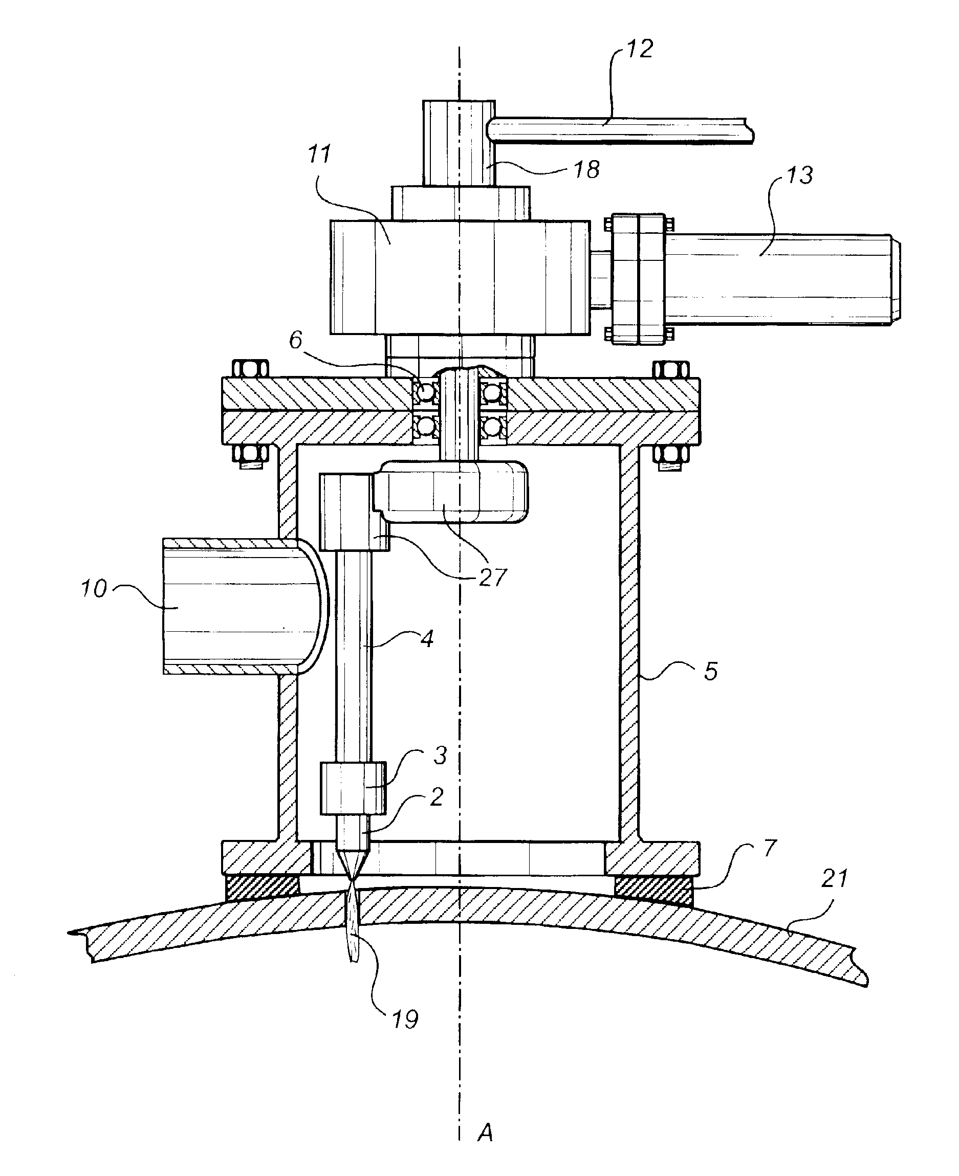
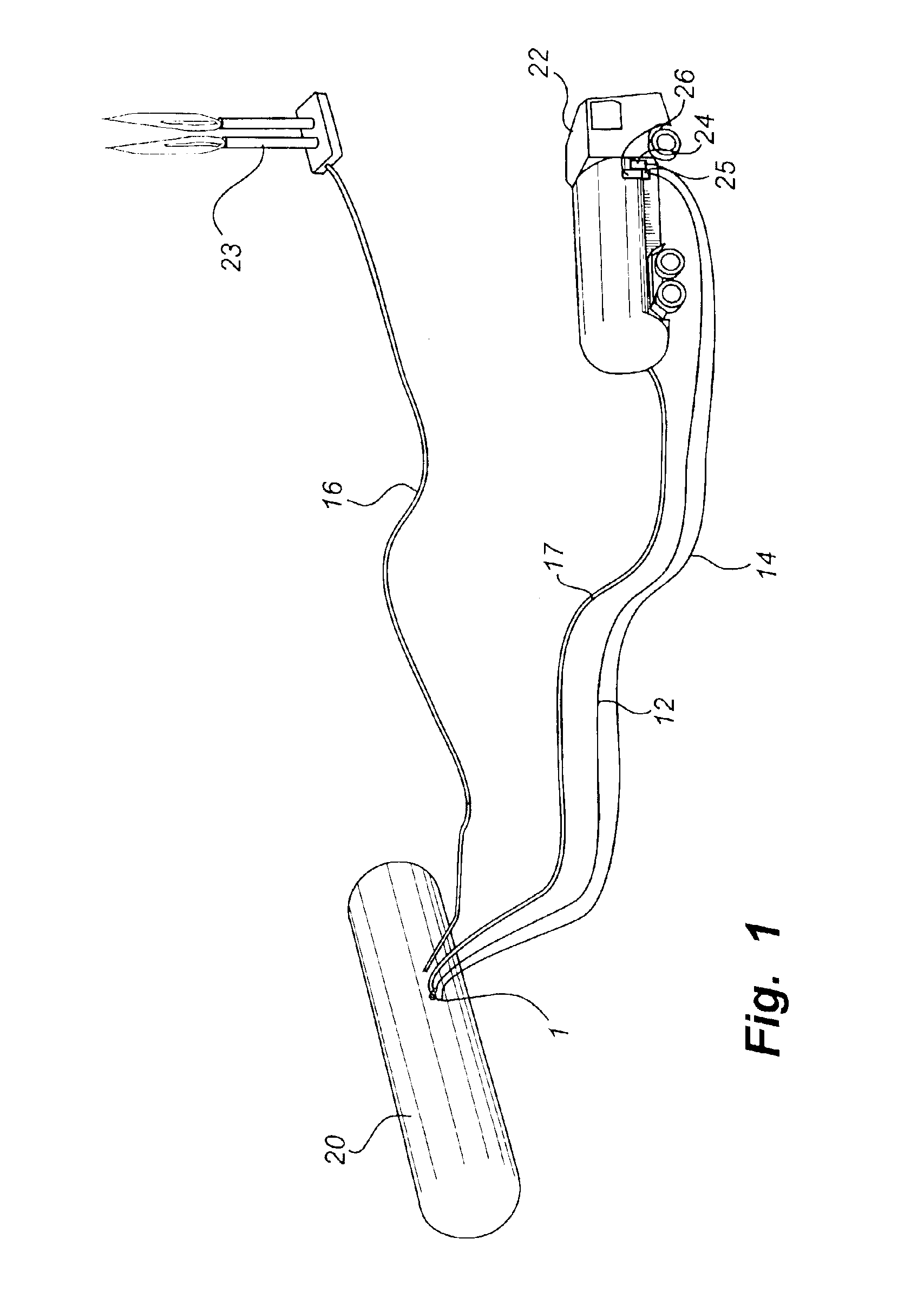
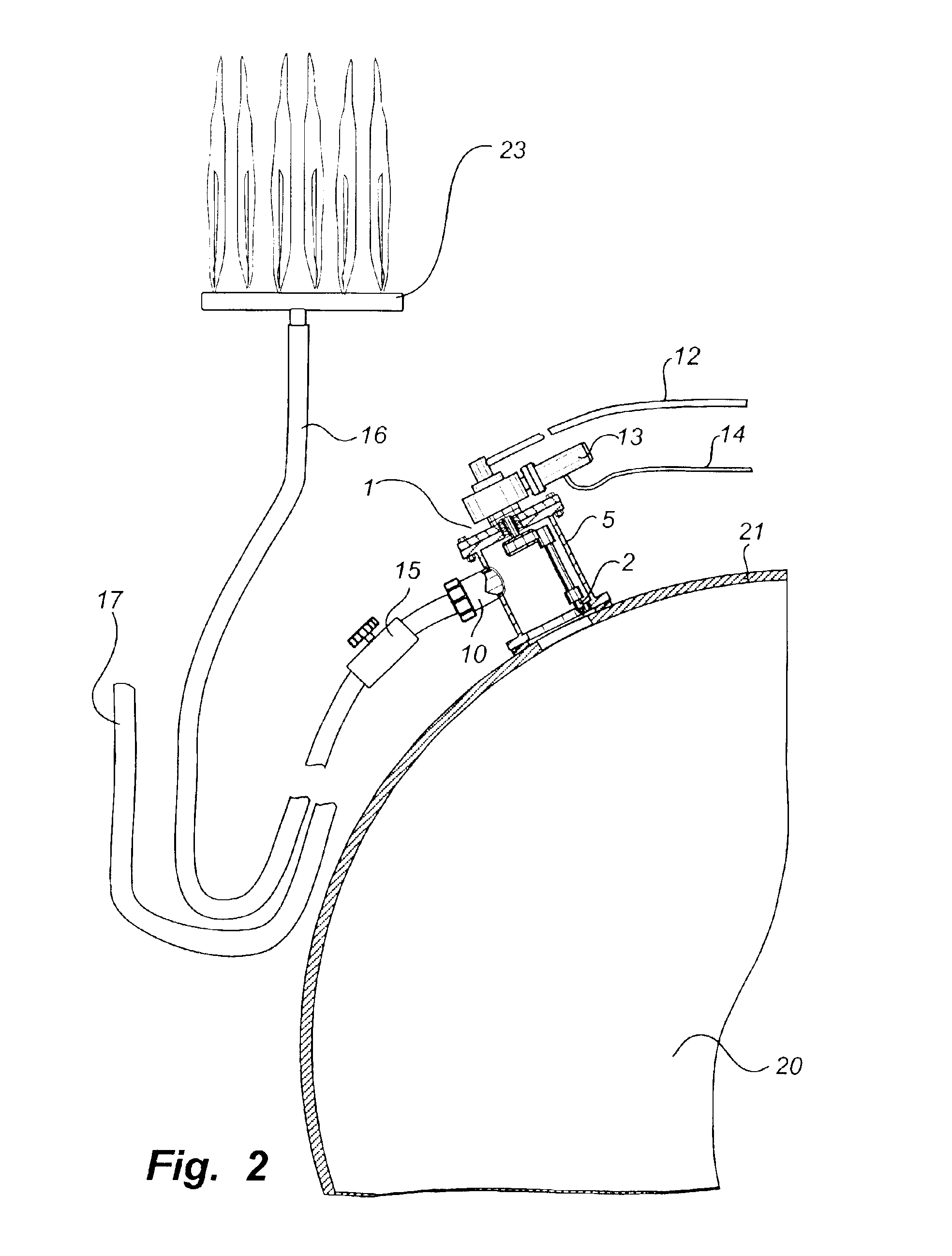
[0025]FIG. 1 illustrates schematically an arrangement of means for evacuation of the contents of a tank 20. A tank car 22, comprising a control centre 25 for controlling a hole-cutting tool 1, is positioned at a point spaced from the tank 20 concerned. The control of the hole-cutting tool 1 may be effected by transfer of signals between the control centre 25 and the hole-cutting device 1 wireless-fashion or via a cable 14.

[0026]In accordance with the preferred embodiment shown and described herein, the pressure source preferably is a motor-driven high-pressure pump 24. The motor could be a hydraulic motor, which in turn is powered by a pump or an engine, not shown, such as a combustion engine. The motor as well as the high-pressure pump 24 are of more or less conventional design and are installed in the tank car 22 shown in the drawing figure. The capacity of the high-pressure pump 24 is such as to enable it to discharge the pressurised medium at a pressure in the range of 100-300 b...


PUM

PropertyMeasurementUnit
Pressureaaaaaaaaaa
Areaaaaaaaaaaa
Forceaaaaaaaaaa

Abstract

A tool and a method for cutting holes in a container wall such as in a tank, a cistern, a pipeline, a vehicle, a ship, a production like or the like that contains inflammable, explosive, or other hazardous gasses, and liquids. The tool includes means for pressurising a cutting medium and discharging said medium via a nozzle. The nozzle is arranged in an enclosing cover including a scalable safety outlet for evacuation of the container contents. The cover has means of sealed-off abutment against the container wall concerned in the area in which hole cutting is to be performed. The nozzle is arranged to be directed towards the container wall in such a way that in use the cutting medium is discharged in the form of a jet impinging against the container wall with sufficient force to cut through said wall.

Description

TECHNICAL FIELD OF INVENTION[0001]The present invention relates to a tool for cutting holes in container walls, such as in tanks, cisterns, reservoirs, pipelines, vehicles, boats, production lines or the like that contain inflammable, explosive or other hazardous gases and liquids.BACKGROUND OF THE INVENTION[0002]In connection with accidents involving for example tank cars, gas tanks, cisterns, pipelines, production lines and the like it is often necessary to evacuate their contents before normal safety measures can be initiated. The work involved in the evacuation of inflammable, explosive or other hazardous and perilous gases and liquids constitutes a considerable hazards both to persons actively taking part in the rescue work and to persons present in the immediate surroundings.[0003]Rescue methods according to prior-art technology therefore often involve vacating people from the immediate surroundings, which could be quite an extensive operation in case the accident occurs for e...

Claims


Application Information

Patent Timeline
IPC IPC(8): B24C3/00B24C1/04B24C1/00B24C3/06B26F3/00B23P17/00
CPCB24C1/045B26F3/004B24C3/065Y10T83/364
Inventor LARSSON, LARS G.
Owner COLT CUT SYST SVENSKA
Why Eureka
Try Eureka