Athermal interferometer

a technology of optical interferometer and thermal interferometer, which is applied in the field of optical interferometer, can solve the problems of providing this kind of accuracy, reducing the air gap of the arm accommodating the tuning plate, and optical path mismatch

Inactive Publication Date: 2005-06-21
LUMENTUM OPERATIONS LLC
View PDF3 Cites 10 Cited by
  • Summary
  • Abstract
  • Description
  • Claims
  • Application Information

AI Technical Summary

Benefits of technology

[0023]wherein the tuning plate means is oriented so that the fixed plate means and the tuning plate...

Problems solved by technology

Typically, beamsplitters available for use in interferometers do not provide this kind of accuracy, and therefore create an optical path mismatch because the divided sub-beams do not travel t...

Method used


Image

  • Athermal interferometer
  • Athermal interferometer
  • Athermal interferometer

Examples


Embodiment Construction

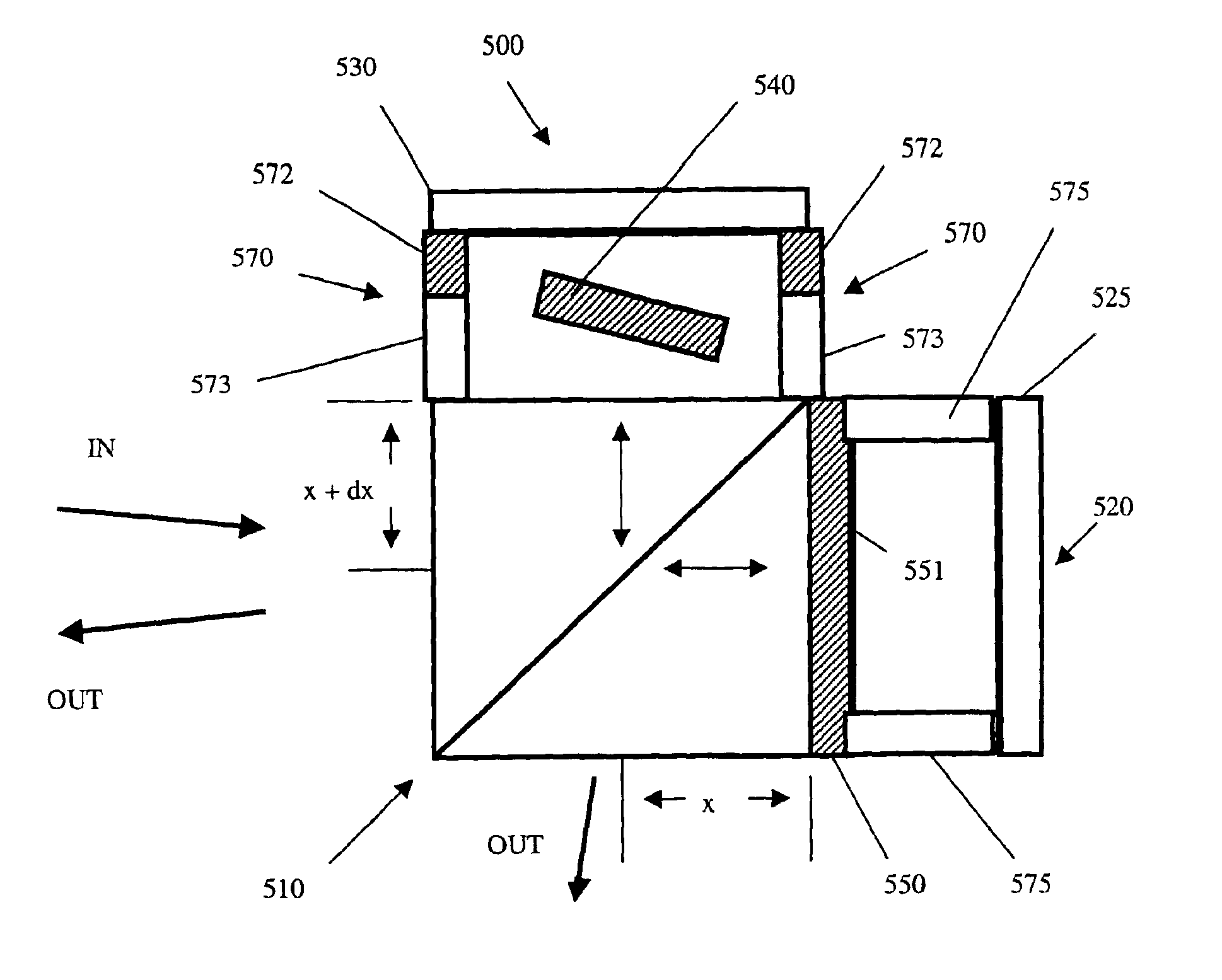
[0034]In the following description, numerous specific details are set forth such as examples of specific materials, components, dimensions, etc. in order to provide a thorough understanding of the present invention. It will be apparent; however, to one skilled in the art that these specific details need not be employed to practice the present invention. In other instances, well known materials or methods have not been described in detail in order to avoid unnecessarily obscuring the present invention. Unless otherwise specified, the components discussed herein may be obtained from industry manufacturers such as Research Electro Optics of Boulder, Colo.

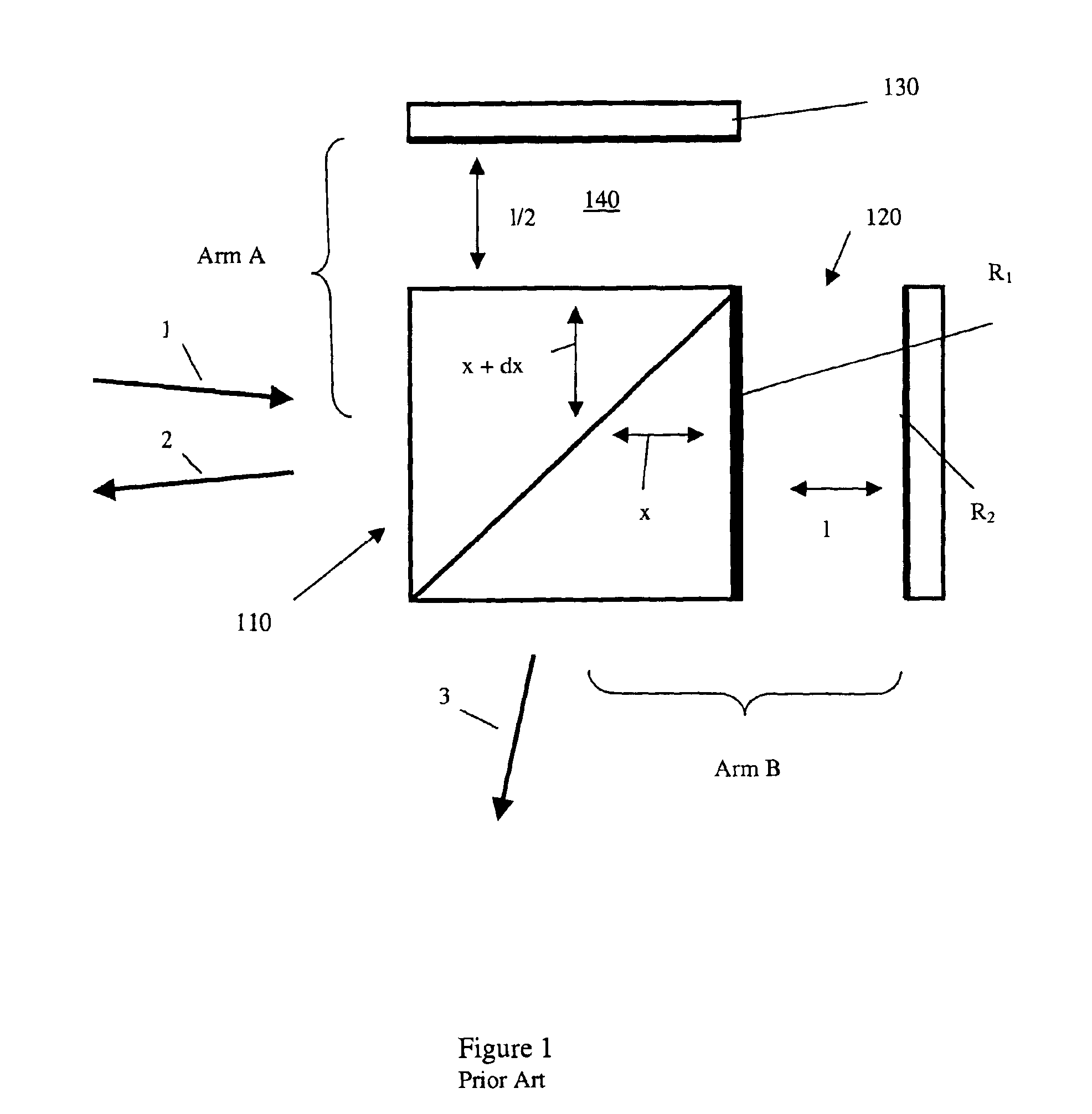
[0035]Referring to FIG. 1, a conventional MGTI includes a cubic beamsplitter 110, a highly reflective (95%-100%) reflecting mirror 130, and a GT etalon 120. The GT etalon 120 has a cavity length (l) such that the etalon's free spectral range (FSR) matches the ITU frequency grid. The front reflective surface R1 of the GT etalon 120 can ...


PUM


Abstract

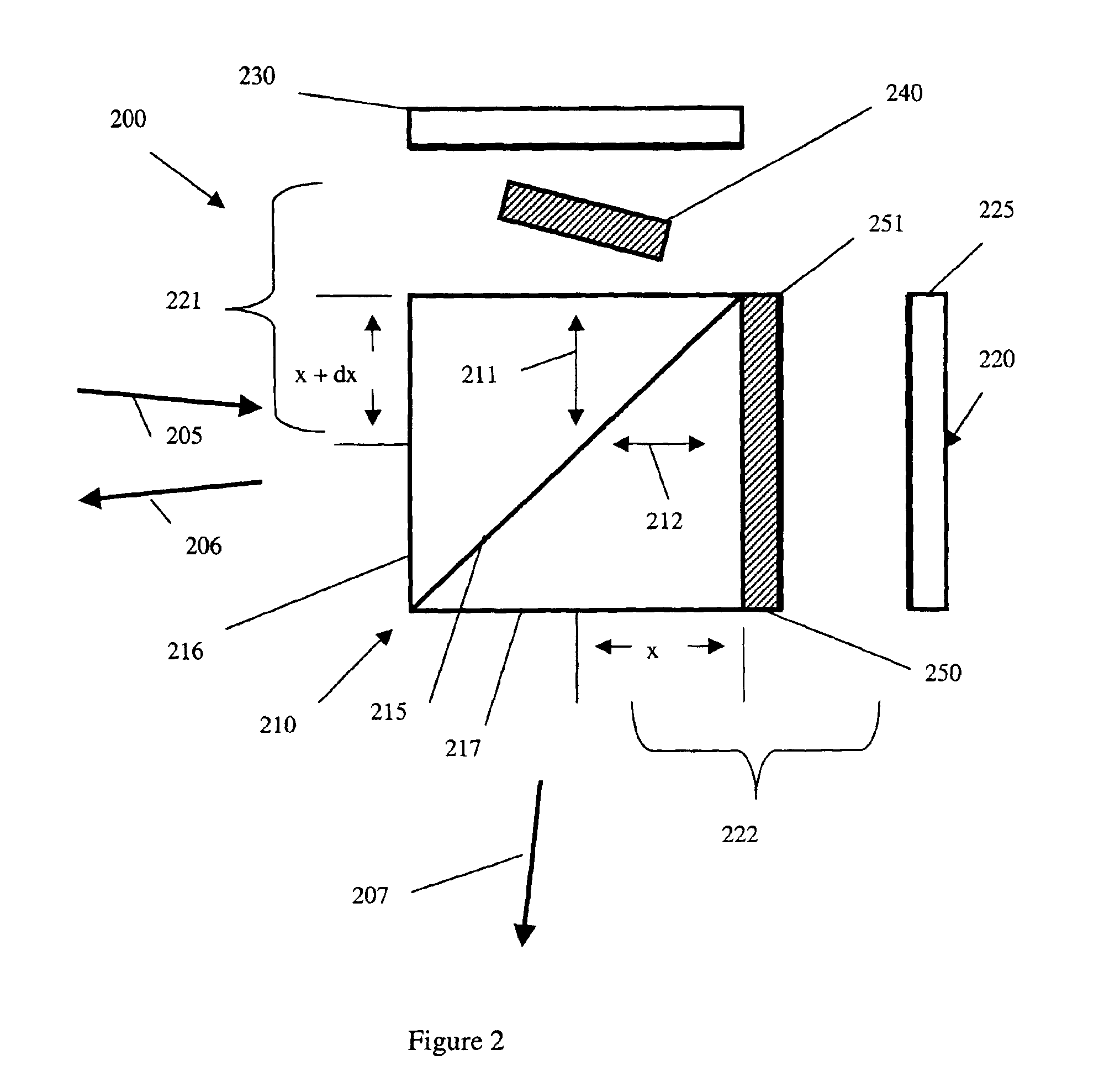
An apparatus is described for controlling the optical path length in an optical device, e.g. an interferometer, and more importantly to maintaining the optical path length difference in an interferometer. The apparatus may include an adjustable plate optically coupled with a beamsplitter. The plate may be rotated such that its surface receives light propagated from the beamsplitter at a non-zero incident angle. In one embodiment, temperature sensitivity is addressed by ensuring that the refractive index of the plate is greater than the refractive index of the beamsplitter. In another embodiment, the apparatus includes combination spacers having a component selected in dependence upon a composition, thickness, and orientation of the adjustable plate.

Description

CROSS-REFERENCE TO RELATED APPLICATIONS[0001]The present application claims priority from U.S. patent application Ser. No. 60 / 271,428 filed Feb. 27, 2001.TECHNICAL FIELD[0002]This present invention relates to an optical interferometer, and in particular to an athermal optical interferometer useful for filtering signals in optical communication networks.BACKGROUND OF THE INVENTION[0003]In multiplexed optical communication networks a single optical fiber typically carries multiple independent data channels, with each data channel assigned to a different optical wavelength. Such networks are referred to as wavelength division multiplexed (WDM) networks. As signals propagate through the network, data in different channels may be separated using various kinds of optical frequency filters, e.g. a deinterleaver.[0004]Optical frequency interleavers / deinterleavers are widely recognized as key components enabling the rapid expansion of WDM networks to higher channel counts and narrower channe...

Claims


Application Information

Patent Timeline
IPC IPC(8): G02B6/34
CPCG02B6/29349G02B6/29398G02B6/29395G02B6/29358
Inventor COPNER, NIGELCOHEN, ADAM D.TAN, KIM L.ABRAHAM, CHRISTOPHER JOHNLAPINSKI, FELIKS
Owner LUMENTUM OPERATIONS LLC
Why Eureka
Try Eureka