
Quasi active power factor correction circuit for switching power supply

a technology of active power factor and switching power supply, which is applied in the direction of electric variable regulation, process and machine control, instruments, etc., can solve the problems of increased manufacturing cost, complex control of active pfc, and lower efficiency of active pfc circuit than one of passive pfc circui

Inactive Publication Date: 2005-06-21
WENG DA FENG
View PDF8 Cites 36 Cited by
  • Summary
  • Abstract
  • Description
  • Claims
  • Application Information

AI Technical Summary

Benefits of technology

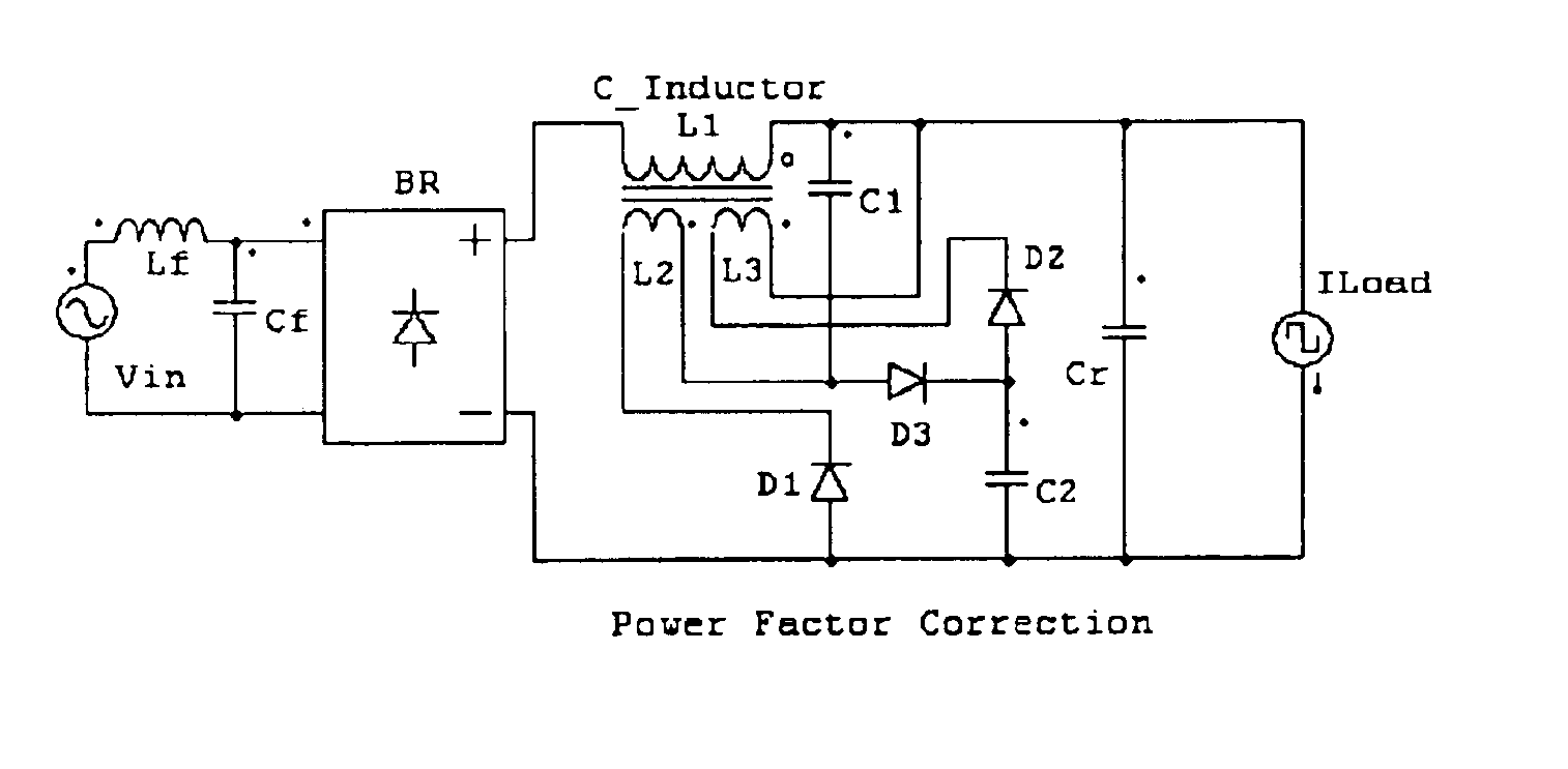
[0020]According to another advantage of the present invention, the current slew rate limiting device comprises an electromotive force generator, such as, for example, the couple inductors.
, the current slew rate limiting device comprises an electromotive force generator, such as, for example, the couple inductors.

Problems solved by technology

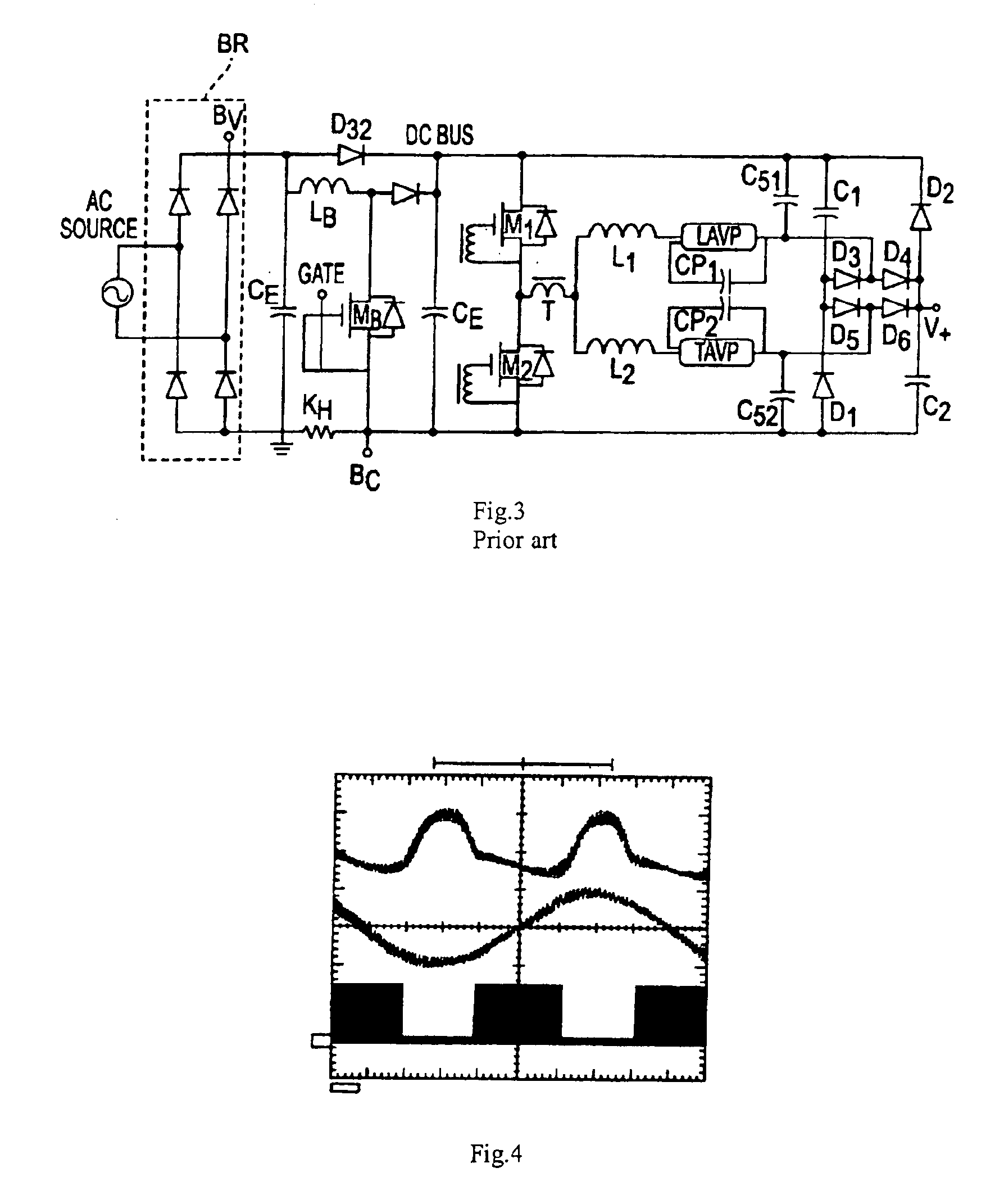
However, the efficiency of the active PFC circuit is lower than one of passive PFC circuit, due to extra switching circuit.
Further, the control of the active PFC is complicated, resulting in increased manufacturing cost and reduced reliability of the circuit.
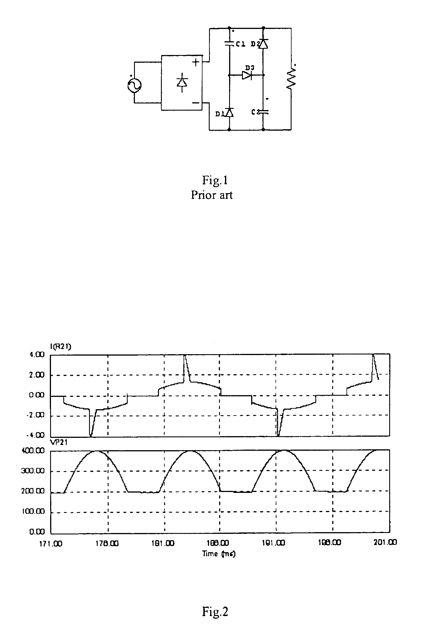
Problems with the valley-fill circuit are a pulsating line current charges the capacitors near the peak power line voltage, resulting in a deteriorated PF (of about 0.95) and a high THD (e.g. about 40%).
Because a boost switch still suffers the peak input voltage and the switch only works during the 60 degree dead time, as shown in FIG. 4, a complex control method is required to detect the operating point.
In addition, the complexity of the circuit decreases the reliability and increases the total manufacturing cost.
However, this disclosure fails to solve the above-described problem that exists at the input current during the approximate 60 degree dead time near the zero line crossing points.
The cost of the disclosure is still high.

Method used


Image

  • Quasi active power factor correction circuit for switching power supply
  • Quasi active power factor correction circuit for switching power supply
  • Quasi active power factor correction circuit for switching power supply

Examples


second embodiment

[0057]the present invention is illustrated in FIG. 9. In this embodiment, a buck circuit 100 is provided as a following power stage, in which the buck circuit works in a continuous or discontinues current mode.

third embodiment

[0058]FIG. 10 illustrates the present invention. In this embodiment, a discharge lamp, such as, for example, a high intensity discharge (HID) lamp is driven by the PFC converter. A full bridge inverter 200 outputs a low frequency square AC current source.

fourth embodiment

[0059]FIG. 11 illustrates the present invention. In this embodiment, a half bridge 300 is employed (used) to drive the discharge lamp, such as, for example, a fluorescent lamp, with a high frequency sinusoidal AC current.

[0060]FIGS. 12 to 18 illustrate the fifth, sixth, seventh, eighth, ninth, tenth and eleventh embodiments of the present invention. In the fifth embodiment (FIG. 12), the PFC converter is interfaced to a discontinues current input buck-boost converter 400. The sixth embodiment (FIG. 13) illustrates the PFC converter of the present invention being interfaced to a discontinues current input flyback converter 500. The seventh embodiment (FIG. 14) illustrates the PFC converter of the present invention being interfaced to a discontinues current input forward converter 600. The eighth embodiment (FIG. 15) illustrates the PFC converter of the present invention being interfaced to a two-switch forward converter 700. The ninth embodiment (FIG. 16) illustrates the PFC converte...


PUM


Abstract

A switching power supply AC-DC-DC or AC-DC-AC with power factor corrector function is provided. The switching power supply circuit includes a quasi active shaping function that shapes an input current of a power line. In the whole system, the active switch or switches are only used to control the output power and no more current stress on the active switch or switches. It is possible to minimize the whole system size.

Description

BACKGROUND OF THE INVENTION[0001]1. Field of the Invention[0002]The present invention is relative to single phase AC to DC converter with power factor correction function (so that the power factor of the input current is at a power factor in excess of that of an otherwise comparable low-power-factor converter design). It can be used on in switching mode power supply and electronics ballast.[0003]2. Description of the Prior Art[0004]The demand for and development of power factor correction (PFC) circuit has been fueled by a concern over the massive use of electronics power converter, such as, AC-DC-DC, AC-DC-AC employed in switching mode power supply system. Due to cost and efficiency consideration, it is desirable to employ a simple PFC circuit and increase the efficiency of the whole system.[0005]PFC circuits are classified into two groups. First group is defined as active PFC circuits, and second group is defined as passive PFC circuits. The very popular Boost-type PFC circuit is ...

Claims


Application Information

Patent Timeline
IPC IPC(8): H02M1/00H02M1/42H02M3/335
CPCH02M1/425H02M3/335Y02B70/1433Y02B70/126Y02B70/10
Inventor WENG, DA FENG
Owner WENG DA FENG
Learn More