Wavelength separation elements for dense wavelength division multiplexing systems

a wavelength division multiplexing and wavelength separation technology, applied in the direction of optical elements, multiplex communication, instruments, etc., can solve the problem of the theoretical limit of >10 tbits/s for a single fiber cable link, and the inability to fully utilize bandwidth

Inactive Publication Date: 2005-06-21
GENERAL ATOMICS
View PDF2 Cites 2 Cited by
  • Summary
  • Abstract
  • Description
  • Claims
  • Application Information

AI Technical Summary

Benefits of technology

[0010]It is an object of the present invention to improve the design of passive multiplexing or demultiplexing devices and systems.
[0011]It is another object to provide greater control over the separation (or combination) properties of the individual wavelength channels of passive multiplexing or demultiplexing devices.
[0012]Still another object is to provide more flexibility in the number and spacing of channels that can be separated or combined and result in lower losses for passive multiplexing or demultiplexing devices.
[0014]The chromatic dispersion properties of a grating can be used to separate individual channels of a DWDM system by causing each channel to be diffracted at a different angle. This process causes a spatial separation of the channels (wavelengths) at a later image plane, so that each can be coupled into a different fiber optic. These systems can also be used in reverse, where the light from individual channels are combined into one fiber by using the chromatic dispersion properties of a grating to re-direct each channel by a predetermined amount. Gratings have many advantages over other channel separation / combination methods because the inherent angular separation of the channels can be directly scaled for increasing channel number and decreasing channel spacing systems by changing the position of the output plane.
[0016]One solution to this problem is to create a system that disperses the wavelength bands corresponding to the channel centers at a faster rate than the bandwidth of the channels themselves. This can be achieved by using a double element system consisting of a grating, to create the initial separation, and a segmented mirror with multiple flat facets of different tilt, which reflect each spatially separated channel at a different angle. The size, position and angle of the facets are designed to match the spacing and position of individual channels of known wavelength and number that are diffracting from a grating with a predefined period, a set distance from this device. The tilts induced by each facet of the segmented mirror do not depend on the wavelength separation, which is the case for the grating and is sub-nanometer between channels for DWDM systems, and so can be much greater than the dispersion of the grating. This system enables the individual channels to be re-imaged at some later point with a large separation between the channels, relative to their spatial size.

Problems solved by technology

The amount of data that can be transferred using an optical fiber is based on the bandwidth that the fiber can support This value can be very large for modern fibers, leading to a theoretical limit of >10 Tbits / s for a single fiber cable link.
However, in practice this bandwidth cannot be fully utilized, primarily due to electronic limitations in the generation and reception of laser beams modulated at this very fast rate.

Method used


Image

  • Wavelength separation elements for dense wavelength division multiplexing systems
  • Wavelength separation elements for dense wavelength division multiplexing systems
  • Wavelength separation elements for dense wavelength division multiplexing systems

Examples


Embodiment Construction

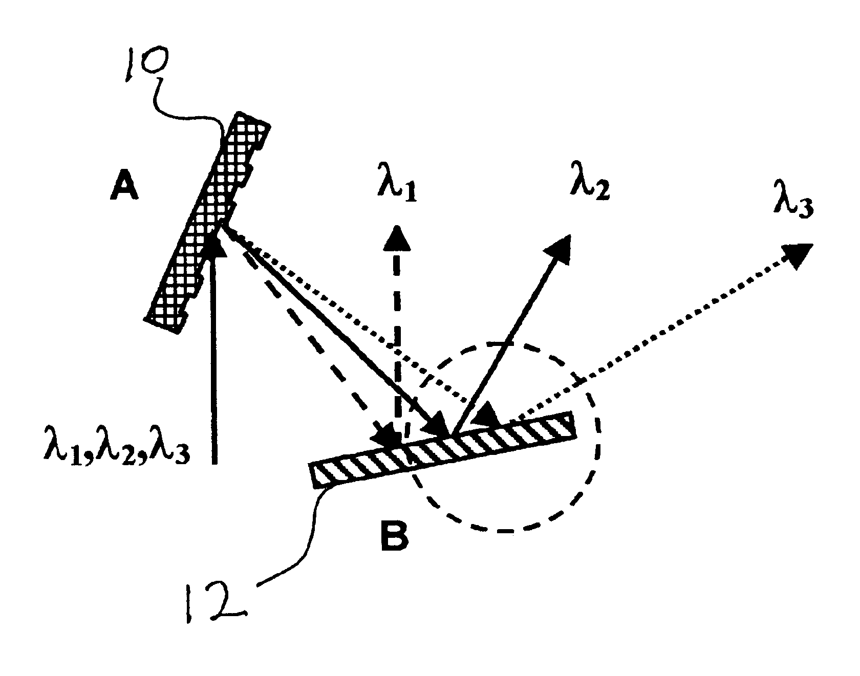
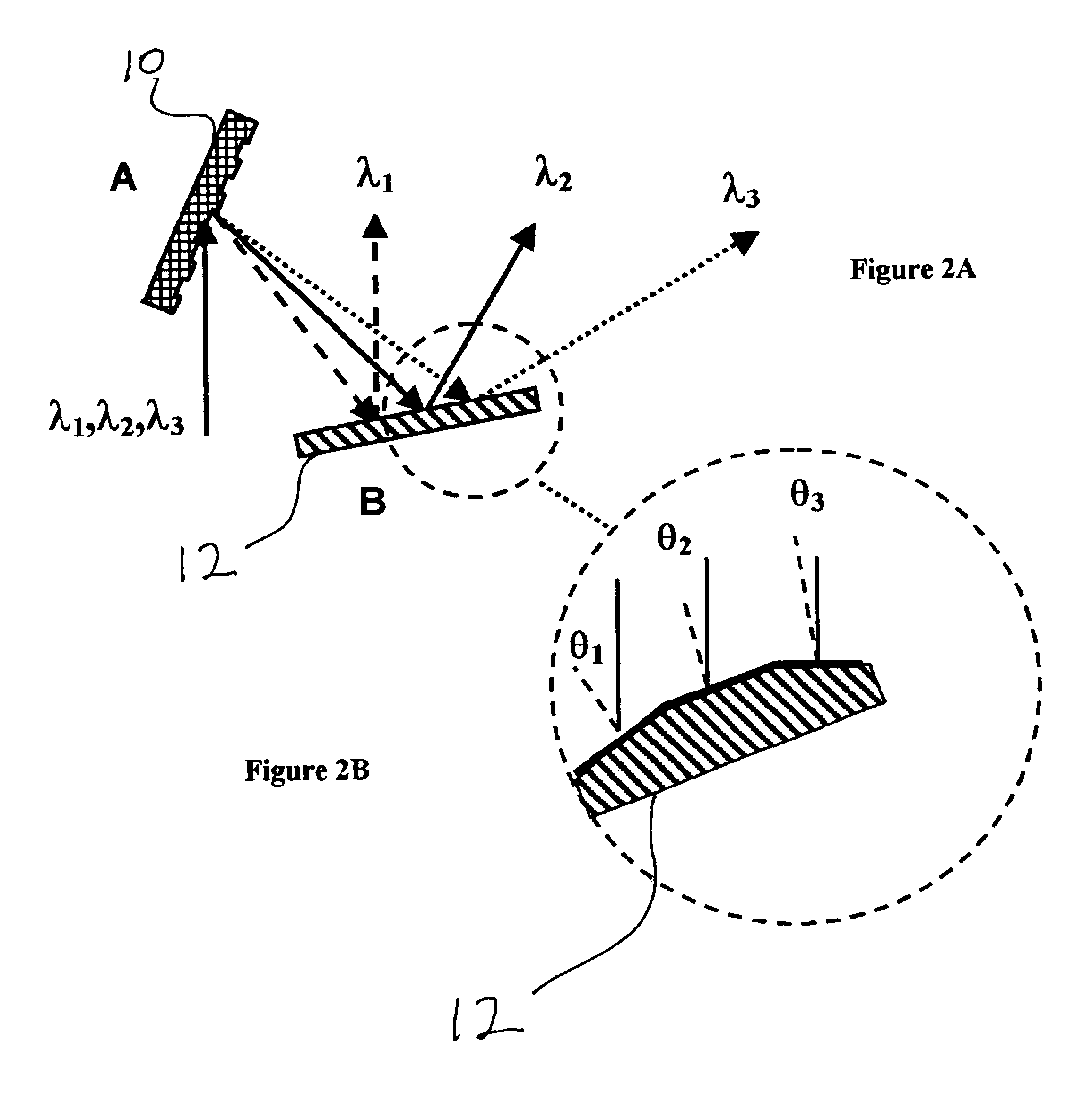
[0021]The invention consists of an optical multiplexer / demultiplexer that separates multiple channels of laser light, each with a different wavelength, co-propagating in an optical fiber, into multiple individual fibers (or the reverse operation). The multiplexing and demultiplexing operations are exactly opposite functions, and so the physics for each are the same, with only the operation being reversed, hence the demultiplexing will be considered here and represent both devices. The elements of an embodiment of the invention are:[0022]An optical fiber termination point;[0023]A chromatically dispersive element that redirects the angular profile of light incident upon it by an amount that is dependent on the wavelength, e.g., a diffraction grating;[0024]A second spatially dispersive element that uniformly redirects the angular profile of sections of the light incident upon it based on the spatial position of the beam incident on it, e.g., a mirror composed from multiple flat segment...


PUM


Abstract

Systems are described that disperse the wavelength bands corresponding to the channel centers at a faster rate than the bandwidth of the channels themselves. An embodiment consists of a double element system including a grating, to create the initial separation, and a segmented mirror with multiple flat facets of different tilt, which reflect each spatially separated channel at a different angle. The size, position and angle of the facets are designed to match the spacing and position of individual channels of known wavelength and number that are diffracting from a grating with a predefined period, a set distance from this device. This system enables the individual channels to be re-imaged at some later point with a large separation between the channels, relative to their spatial size.

Description

[0001]This application claims the benefit of Provisional Application No. 60 / 327,505 filed Oct. 5, 2001.BACKGROUND OF THE INVENTION[0002]1. Field of the Invention[0003]The present invention relates to the field of dense wavelength division multiplexing (DWDM) optical telecommunication components, and more particularly, it relates to passive multiplexing or demultiplexing devices, which separate multiple channels of light co-propagating in one optical fiber into multiple individual fibers (or the reverse).[0004]2. Description of Related Art[0005]The amount of data that can be transferred using an optical fiber is based on the bandwidth that the fiber can support This value can be very large for modern fibers, leading to a theoretical limit of >10 Tbits / s for a single fiber cable link. However, in practice this bandwidth cannot be fully utilized, primarily due to electronic limitations in the generation and reception of laser beams modulated at this very fast rate. Wavelength divisi...

Claims


Application Information

Patent Timeline
Patent Type & Authority Patents(United States)
IPC IPC(8): G02B6/34
CPCG02B6/2938G02B6/2931
Inventor BARTON, IAN MICHAELHERMAN, STEVE MATHEW
Owner GENERAL ATOMICS
Why Eureka
Try Eureka