Contact element and ceiling element for a heating and cooling ceiling

a technology of contact elements and ceiling elements, which is applied in the direction of domestic heating details, space heating and ventilation details, sustainable buildings, etc., can solve the problems of ceiling panels, limitations, and restricted heating and cooling of panels, and achieve improved heat transfer between the contact element and the ceiling panel, improved use effect, and increased contact surface area

Inactive Publication Date: 2005-06-28
BARCOL AIR
View PDF41 Cites 45 Cited by
  • Summary
  • Abstract
  • Description
  • Claims
  • Application Information

AI Technical Summary

Benefits of technology

[0008]The advantages achieved by the invention being that the heat transfer between the contact element and the ceiling panel is considerably improved and consequently, better use can be made of the temperature difference between the room which is to be conditioned climatically and the contact element, the temperature difference being limited by the dew point.
[0009]In addition, the improvements permit an increase in the contact surface area which are possible because it has been found that, due to the poor thermal conductivity of the conventional ceiling panels, the heating and cooling of the panels remains confined essentially to those regions which are located directly beneath the contact element. For this reason, it is desirable to make the contact surface as large as possible. In the case of rigid contact elements, limitations arise due to irregularities of the ceiling panel, in particular due to the bending which is caused by the dead weight of the ceiling panel and the weight of other parts, such as the contact element, bearing on it. Thus, according to a particularly advantageous configuration of the invention, the contact panel is designed to be elastically or plastically deformable, with the result that it adapts to some extent to the ceiling panel, and even a large contact surface bears in its entirety thereon. In addition, such a design of the contact panel, in some circumstances, aids good heat-conducting contact between the ceiling panel and those parts of the contact surface which are not adhesively bonded to said ceiling panel.

Problems solved by technology

In addition, the improvements permit an increase in the contact surface area which are possible because it has been found that, due to the poor thermal conductivity of the conventional ceiling panels, the heating and cooling of the panels remains confined essentially to those regions which are located directly beneath the contact element.
In the case of rigid contact elements, limitations arise due to irregularities of the ceiling panel, in particular due to the bending which is caused by the dead weight of the ceiling panel and the weight of other parts, such as the contact element, bearing on it.

Method used


Image

  • Contact element and ceiling element for a heating and cooling ceiling
  • Contact element and ceiling element for a heating and cooling ceiling
  • Contact element and ceiling element for a heating and cooling ceiling

Examples


first embodiment

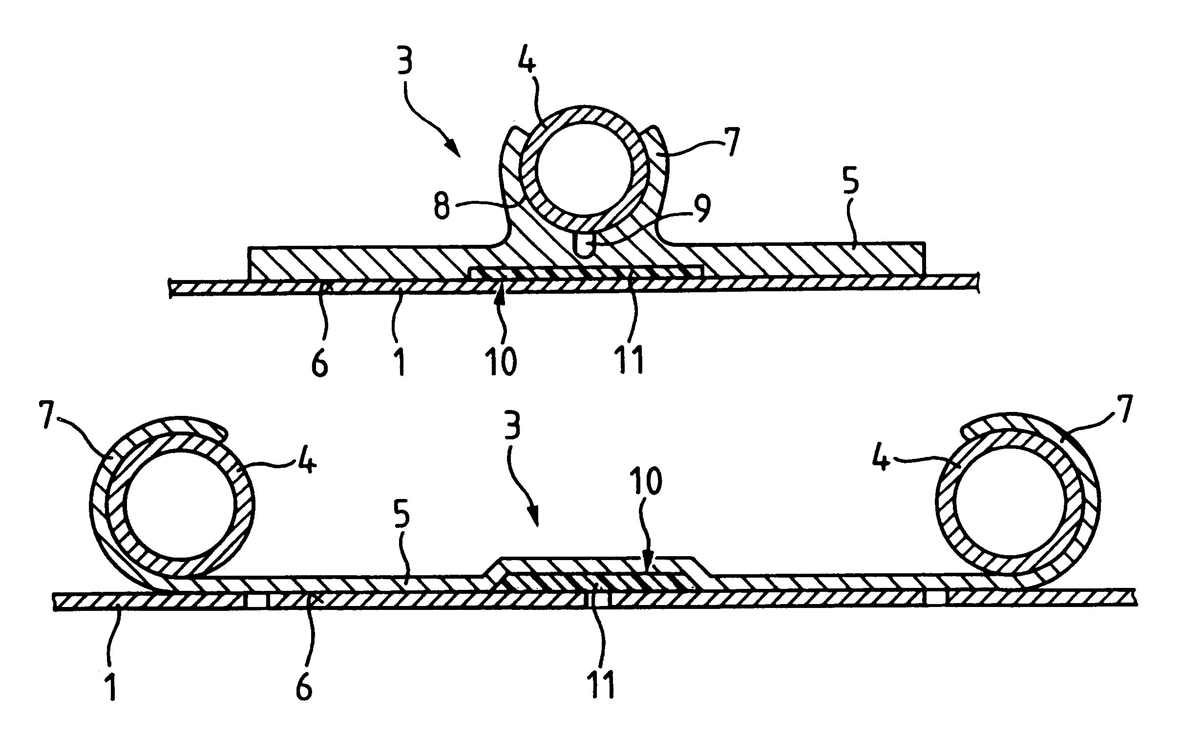
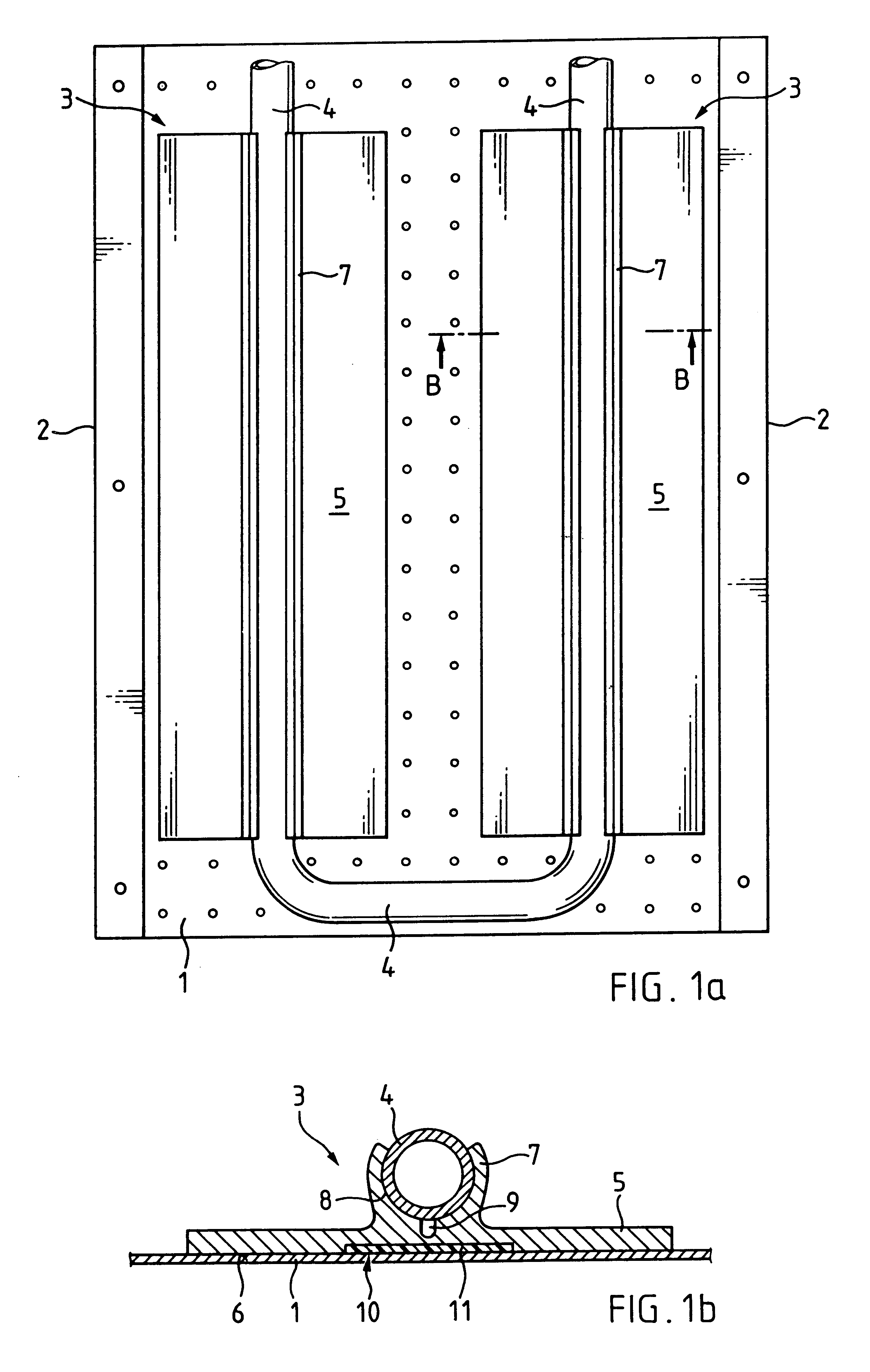
[0018]The ceiling element comprises in each case a ceiling panel 1 which is preferably, but not necessarily, perforated, and is formed of aluminium, preferably sheet aluminium, sheet steel, plastic, gypsum or wood ceiling panel 1 has side flanges 2 which serve for fastening the ceiling panel 1, for example, on the ceiling of a climatically conditioned room. In the ceiling element (FIG. 1a, b), two contact elements 3 are arranged in parallel on the upper side of the ceiling panel 1 and have a U-shaped pipe 4 of copper, steel or plastic drawn through them.

[0019]The contact element 3 is made from a strong, preferably metallic material. In the first embodiment is preferably extruded from aluminium. It has a rectangular contact panel 5 whose underside forms an essentially planar contact surface 6, while a guide 7 is arranged on the upper side. Guide 7 forms an upwardly open channel 8 into which the pipe 4 is drawn or pressed. On the base of the channel 8 is a bending groove 9 which is co...

third embodiment

[0024]In the contact element (FIGS. 3a, b), three contact elements 3 are arranged on the upper side of the ceiling panel 1 and have the pipe 4 drawn through them in a meandering fashion, two parallel pipe sections being guided in each contact element 3.

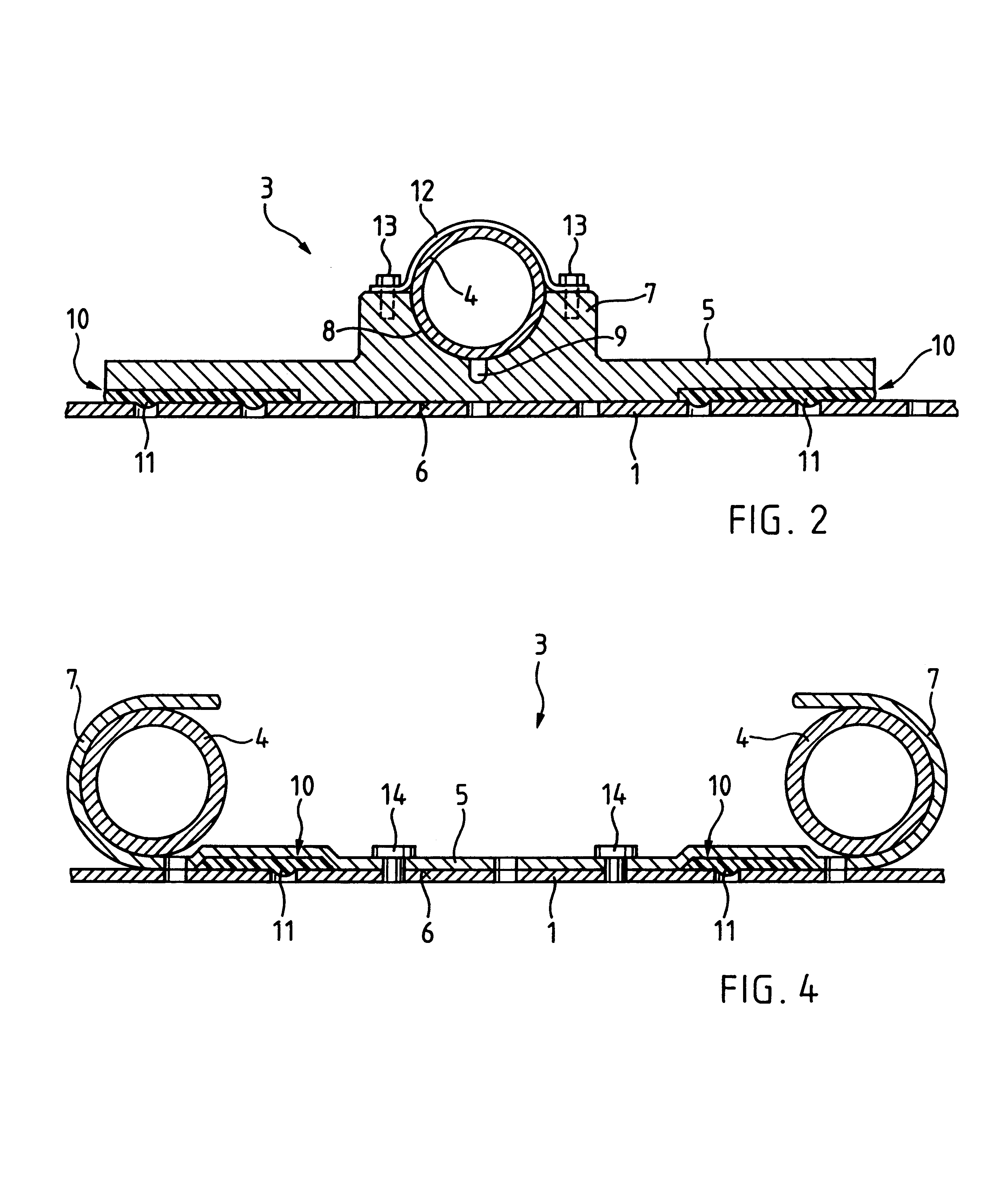
[0025]The contact element 3 is produced in each case from a strip of sheet metal, which preferably consists of an elastic copper alloy, e.g. copper / beryllium, but may also consist of aluminium, and forms a contact panel 5 which is bent over at borders 15 to form guides 7 which enclose the pipe 4 on an outer side thereof. The guide 7 is designed in each case such that it encloses the pipe 4 on the outer half of the pipe and presses elastically on pipe 4. With slight outward bending of the guides 7, the pipe 4 can be pushed into guide 7. The guides 7 may also be designed such that they extend only slightly beyond half the height of the pipe 4, with the result that the pipes can be snap-fitted into the guides 7 from above.

[0026]The conta...

fourth embodiment

[0027]In the contact element (FIG. 4), the contact element 3 is produced from sheet copper or sheet aluminium and, once again, has two guides 7 which are formed by the contact panel material being bent over at the borders 15 such that they may rest against the outer half of the pipe 4. The internal diameter of the guides 7 may be selected to be slightly smaller than the external diameter of the pipe 4, with the result that guides 7 are deformed slightly when the pipe is pushed in and thus good contact between the guide 7 and the pipe 4 is then ensured.

[0028]The contact panel 5 has two flat indents which form, in the border regions 17 of the contact surface 6, strip-like adhesive depressions 10 which are continuous in the longitudinal direction. The adhesive depressions 10 are relatively narrow, with the result that the entire adhesive surface area takes up considerably less than half of the contact surface area 6. Prior to the adhesive bonding to the ceiling panel 1, the contact pan...


PUM


Abstract

In order to improve the heat-conducting connection between a contact element (3) and a ceiling panel (1) which are adhesively bonded to one another, the contact panel (5) of the contact element (3) is provided with an adhesive depression (10) in the contact surface (6), said depression taking up only part of said contact surface, while the remaining part of the latter rests directly against the upper side of the ceiling panel (1). The contact panel (5) may be elastically or plastically deformable, e.g. along a bending groove (9), with the result that it adapts more easily to irregularities, such as those caused, for example, by slight sagging of the ceiling panel (1). This permits larger widths of the contact panel (5) without impairing the thermal contact. In order to ensure close abutment of the parts of the contact surface (6) which are not adhesively bonded to the upper side of the ceiling panel (1), the contact panel (5) can be appropriately prestressed.

Description

BACKGROUND OF THE INVENTION[0001]1. Field of the Invention[0002]The present invention relates to a contact element for providing heat transfer from a heat transfer medium to a ceiling and to a ceiling element which comprises such a contact element.[0003]2. Description of the Related Art[0004]Various configurations of contact and ceiling elements which can be used for heating ceilings and cooling ceilings and for ceilings which are intended for both heating and cooling are known. A number of such configurations are described in H. Sokolean: “Kühldeckentechnologie zur Erreichung des bestmöglichen Raumkomforts” [Cooling-ceiling technology for achieving the best possible interior conditions], Architektur und Technik 8 / 92, p. 49-53, B+L Verlags AG, Schlieren (Switzerland).[0005]One of the basic problems of ceiling elements of the type mentioned here has been the task of always ensuring good heat transfer between a heat transfer medium, usually a liquid, which flows through the element, a...

Claims


Application Information

Patent Timeline
Patent Type & Authority Patents(United States)
IPC IPC(8): F24D3/16F28F1/12F28F1/22F24F5/00F24D3/12
CPCF24D3/165F24F5/0089F28F1/22F24F5/0092F24F13/24F28F2275/025Y02B30/00
Inventor SOKOLEAN, HELMUTH
Owner BARCOL AIR
Why Eureka
Try Eureka