
Projection type image display apparatus

a technology of projection and image display, which is applied in the direction of television systems, instruments, color signal processing circuits, etc., can solve the problems of low light utilization efficiency, insufficient brightness, and insatiable contrast, and achieve high contrast, good image quality performance, and satisfactory brightness

Inactive Publication Date: 2005-06-28
HITACHI LTD
View PDF5 Cites 42 Cited by
  • Summary
  • Abstract
  • Description
  • Claims
  • Application Information

AI Technical Summary

Benefits of technology

[0011]The present invention has been made in view of the above problems and aims at providing a light, compact optical unit which uses a reflection image display device to provide satisfactory brightness, high contrast and good image quality performance such as high resolution, and a reflection type image display apparatus which uses the unit.

Problems solved by technology

Also, although the above catalog describes a color wheel as a means to display a color image, the ratio of loss of light passing through the color wheel is 2 / 3 or so and the light utilization efficiency is low, so that sufficient brightness is not obtained unless a high power lamp is used.
Besides, the contrast is not satisfactory and should be improved.

Method used


Image

  • Projection type image display apparatus
  • Projection type image display apparatus
  • Projection type image display apparatus

Examples


Embodiment Construction

[0034]Preferred embodiments of the present invention will be described referring to the accompanying drawings. The components which are common among all the drawings are marked with the same reference numerals and once a component is explained, the explanation will not be repeated.

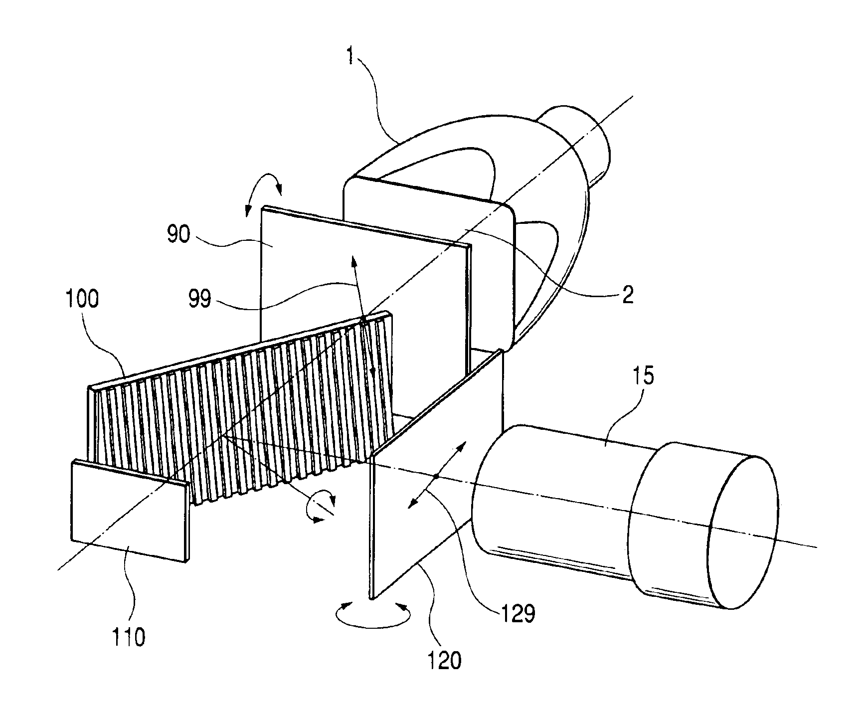
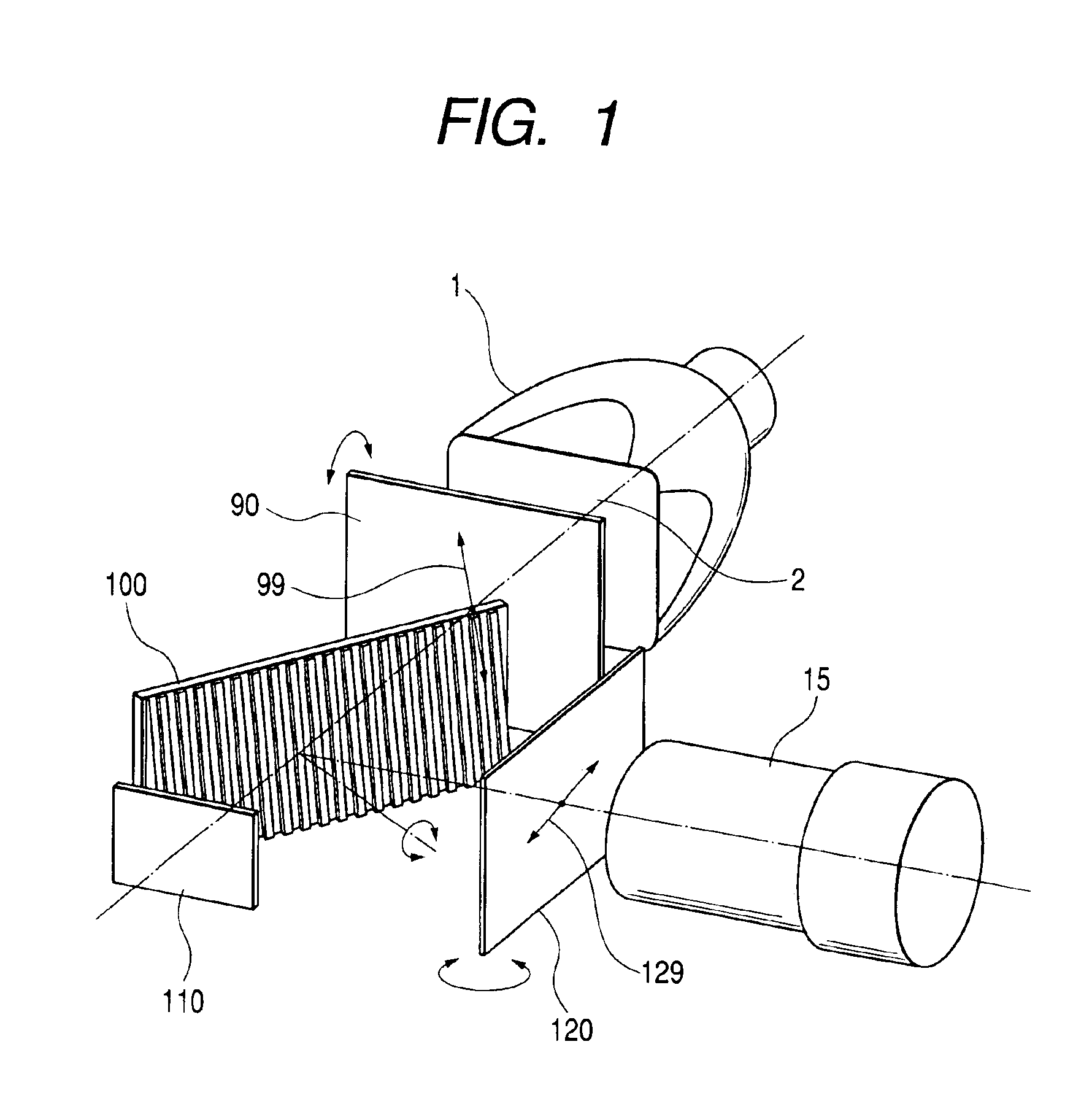
[0035]FIG. 1 shows a projector optical unit according to an embodiment of the present invention.

[0036]In FIG. 1, numeral 1 represents a light source; 2 the optical axis of a reflection type liquid crystal projector optical unit; 90 an auxiliary polarizer for white; 100 a reflection polarizing plate for white; 110 a reflection liquid crystal panel for white; 120 an auxiliary analyzer for white; and 15 a projection lens.

[0037]An explanation is made below with reference to FIG. 1 about how a reflection type liquid crystal projector optical unit in the present invention works.

[0038]For white image display, the operational sequence is as follows. As illustrated in FIG. 1, rays from the light source 1 which are ...


PUM


Abstract

Disclosed is a compact, light, inexpensive reflection type liquid crystal projector optical unit or reflection type liquid crystal projector which provides high brightness without contrast deterioration caused by light leakage associated with black image display. The unit or projector uses, as a polarizer / analyzer for a reflection liquid crystal panel, a reflection polarizing plate which functions as a polarizing plate by its grating function only in a specific direction. It also uses an auxiliary polarizer and an absorption auxiliary analyzer. Their reflection axis or absorption axis is adjusted according to the characteristic of the reflection liquid crystal panel so as to minimize light leakage associated with black image display.

Description

BACKGROUND OF THE INVENTION[0001]The present invention relates to an optical unit which modulates the intensity of a light beam from an illumination optical system by the polarization function of a reflection image display device to make an optical image and projects the image on a screen through a projection optical system, and a projection type image display apparatus which uses the unit.[0002]A popularly known projection type image display apparatus is a projector which has an optical unit housed in a case together with power supply circuitry and image drive circuitry where the optical unit makes an optical image by light intensity modulation and projects the image on a screen through a projection lens. Here, light intensity modulation refers to a process where light from a light source is polarized to change the shading of each picture element according to image signal through a light valve device.[0003]When a reflection liquid crystal panel is used as a light valve device, usua...

Claims


Application Information

Patent Timeline
IPC IPC(8): G03B21/16G02F1/13G02B21/00G02B27/28G02F1/13357G03B21/00H04N5/74H04N9/31
CPCG03B21/16G03B33/12G03B21/208G02B21/00
Inventor NAKASHIMA, TSUTOMUOUCHI, SATOSHIIMAHASE, TAROMIYOSHI, TOMOHIRO
Owner HITACHI LTD
Learn More