Scanline alignment sensors

a technology of alignment sensors and scanning lines, applied in the field of optical imaging systems, can solve problems such as significant residual misalignment, and achieve the effect of eliminating laser safety hazards, repeatable and known alignment precision, and avoiding residual misalignmen

Inactive Publication Date: 2005-06-28
CARESTREAM HEALTH INC
View PDF2 Cites 6 Cited by
  • Summary
  • Abstract
  • Description
  • Claims
  • Application Information

AI Technical Summary

Benefits of technology

[0011]1. Adjustment of the fold mirror can be made without direct observation of the laser beam, eliminating laser safety hazard and providing a repeatable and known alignment precision since the beam is aligned to precision slots in the CR reader.

Problems solved by technology

Also the process resulted in significant residual misalignment since the adjustment process was a subjective operator dependent alignment.

Method used


Image

  • Scanline alignment sensors
  • Scanline alignment sensors
  • Scanline alignment sensors

Examples


Embodiment Construction

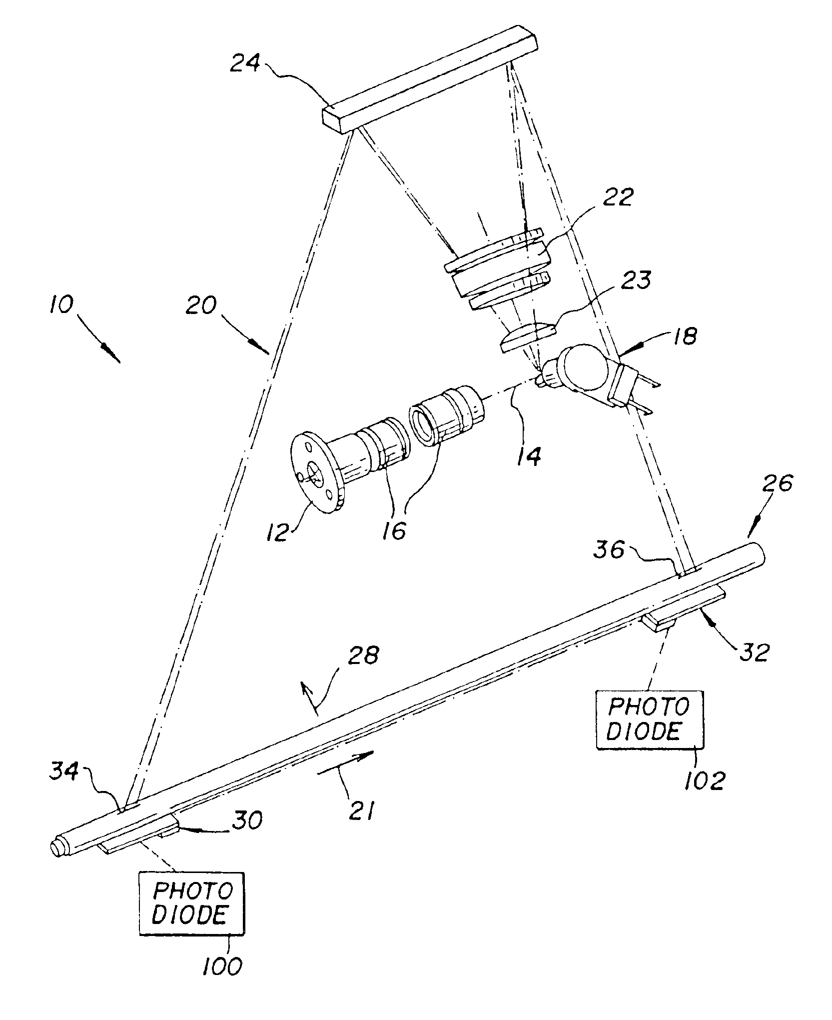
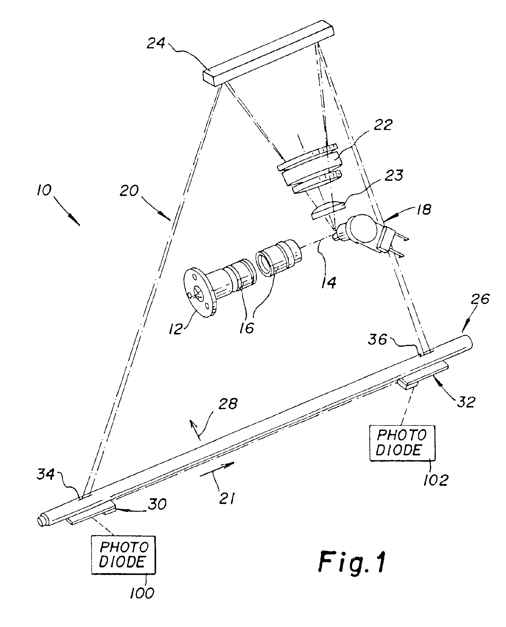
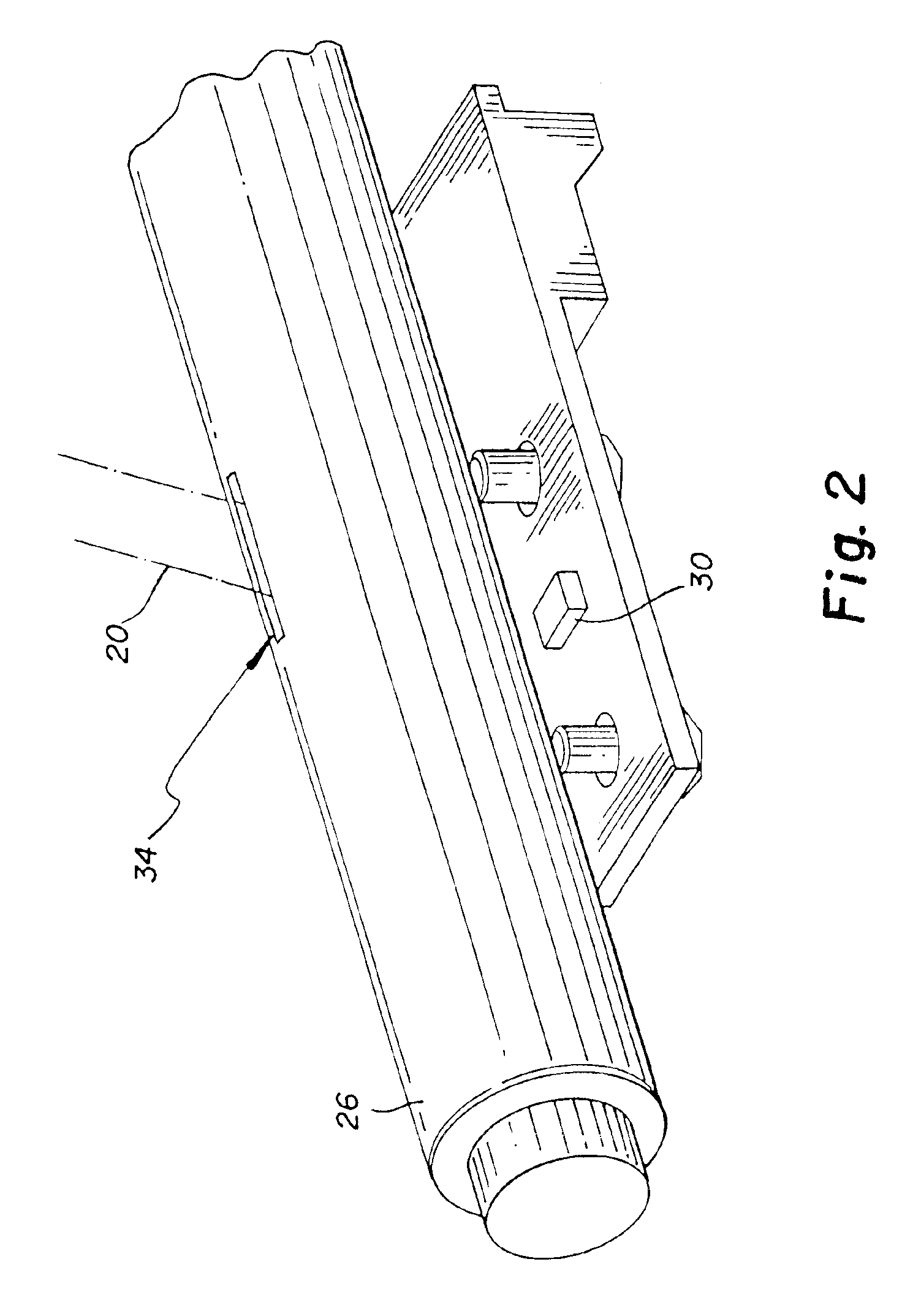
[0021]Referring now to FIGS. 1-3, there is shown a laser scanning optical system for use in a computed radiography scanning system (or any other similar scanning system) incorporating an embodiment of the present invention. As shown, laser scanning optical system 10 includes a laser diode 12 which produces a laser beam 14 shaped by shaper lens elements 16. A reciprocating galvonometer mirror 18 produces a laser beam scan line 20 in a fast scan direction 21 shaped by F-theta lens 22 and lens 23. A final fold mirror 24 directs scan line 20 onto scan platen 26. Scan platen 26 establishes an imaging region for a storage phosphor transported in a slow scan direction 28 over platen 26. Sensors 30 and 32 are located at the ends of scan line 20 and are activated by laser beam 14 passing through respective slots 34 and 36 in platen 26. A rotating multifaceted polygon mirror can also be used in place of the reciprocating galvonometer mirror 18 to produce laser beam scan line 20. According to ...


PUM


Abstract

An optical imaging system comprising: an optical assembly for producing a laser beam scanline at an imaging region; first and second photodetectors located at the imaging region at the first and second ends of a produced laser beam scanline; and a visual indicator system coupled to the first and second photodetectors to visually indicate detection of the first and second ends of the laser beam scanline.

Description

CROSS REFERENCE TO RELATED APPLICATIONS[0001]This is a 111A application of Provisional Application Ser. No. 60 / 444,014, filed 31, Jan. 2003.FIELD OF THE INVENTION[0002]This invention relates in general to optical imaging systems and more particularly to visual aids for facilitating alignment of a laser beam scanline at an imaging region.BACKGROUND OF THE INVENTION[0003]In a Computed Radiography (CR) reader, the laser beam is scanned in a scanline over the surface of a storage phosphor screen by a reciprocating galvanometer mirror or polygon rotating mirror in a fast scan direction while the screen is transported under the scanline in a slow scan direction. To make the CR reader compact and manufacturable, a final fold mirror is placed in the optical path between an F-theta lens and the phosphor screen. The fold mirror introduces three degrees of freedom into the optical system. A coordinate system on the mirror has an x-axis in the plane of the mirror along the fast scan dimension o...

Claims


Application Information

Patent Timeline
Patent Type & Authority Patents(United States)
IPC IPC(8): G01V5/04G02B26/08G01V5/00H01J3/00H01J3/14G02B26/10
CPCG02B26/105
Inventor URBON, MICHAEL P.BAIR, JOHN L.
Owner CARESTREAM HEALTH INC
Why Eureka
Try Eureka