Television receiver

Inactive Publication Date: 2005-06-28
FUNAI ELECTRIC CO LTD
View PDF13 Cites 47 Cited by
  • Summary
  • Abstract
  • Description
  • Claims
  • Application Information

AI Technical Summary

Benefits of technology

[0028]Thereby, it is possible to prevent the display unit from clearing the display memory and the non-display memory, whereby the contents of the display memory

Problems solved by technology

However, there were none of the receivers for digital broadcasting as offered heretofore that output the closed caption data distributed by the DTVCC method along with the picture signal in accordance with

Method used


Image

  • Television receiver
  • Television receiver
  • Television receiver

Examples


Embodiment Construction

[0079]Now, a description will be given in more detail of preferred embodiments of the invention with reference to the accompanying drawings.

[0080]A television receiver (hereinafter simply referred to as a receiver) according to an embodiment of the present invention will be described below.

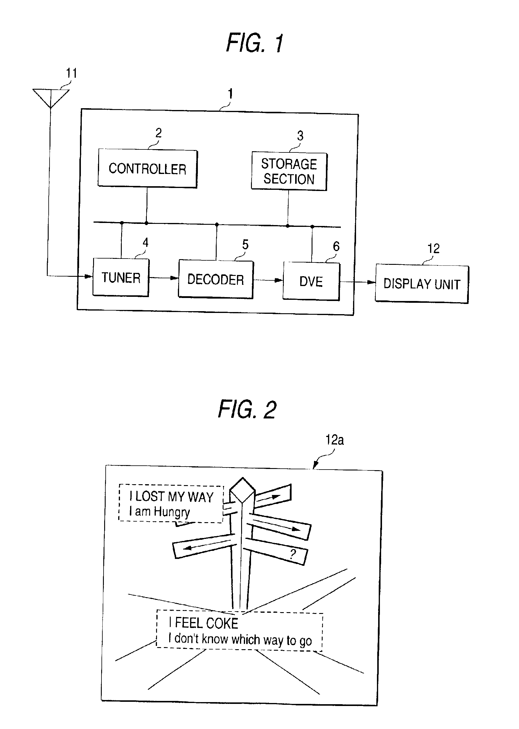
[0081]FIG. 1 is a block diagram showing the configuration of the receiver according to the embodiment of the invention. The receiver 1 comprises a controller 2 for controlling the operation of a main unit, a storage section 3 for storing the data produced in operation, a tuner 4 for taking out a signal of selected channel from a digital broadcasting signal received via an antenna 11, a decoder 5 for extracting a picture signal and the closed caption data from the signal taken out by the tuner 4, and a digital picture encoder (hereinafter referred to as a DVE) 6 for outputting an analog broadcasting signal.

[0082]The DVE 6 is connected with a display unit 12. This display unit 12 is operated in acco...


PUM


Abstract

A television receiver 1 enables a decoder 5 to extract a closed caption signal of DTVCC method from a digital broadcasting signal received via an antenna 11. The closed caption signal of DTVCC method extracted here is analyzed and converted into the closed caption signal of Line 21 method. And in a DVE 6, the closed caption data of Line 21 method is inserted into the 21st scanning line of an analog picture signal converted by the decoder 5 for output.

Description

BACKGROUND OF THE INVENTION[0001]1. Field of the Invention[0002]The present invention relates to a television receiver for receiving the digital broadcasting, and more particularly to a television receiver for receiving the caption broadcasting with the caption data.[0003]2. Description of the Related Art[0004]The conventional television broadcasting was the analog broadcasting of the NTSC (National Television System Committee) system. In the analog broadcasting, the caption broadcasting was made in which a broadcasting station distributes a picture signal and the caption data (closed caption data (CC)). In the analog broadcasting, the closed caption data is distributed in the twenty first scanning line of the picture signal, as standardized in the EIA (Electronic Industries Association)-608. This method of distributing the closed caption data in the twenty first scanning line of the picture signal is hereinafter referred to as a Line 21 method.[0005]This Line 21 method has spread e...

Claims


Application Information

Patent Timeline
IPC IPC(8): H04N7/087H04N7/24H04N7/088H04N5/00H04N5/445H04N7/025H04N7/03H04N7/035
CPCH04N5/4401H04N7/0885H04N21/4355H04N21/4884H04N21/4312H04N21/443H04N21/426
Inventor KATAYAMA, TAKAHIROTAKAGI, TOSHIHIRO
Owner FUNAI ELECTRIC CO LTD
Why Eureka
Try Eureka