Method and device for electronically controlling the beating of a heart

a technology of electronic control and heart rhythm, applied in the field of methods and devices, can solve the problems of irreversible nerve damage, inability to take a viable approach, and the placement of electrodes either around the nerve bundle or into the neural perineum also poses a significant risk

Inactive Publication Date: 2005-06-28
MEDTRONIC INC
View PDF30 Cites 165 Cited by
  • Summary
  • Abstract
  • Description
  • Claims
  • Application Information

AI Technical Summary

Problems solved by technology

However, this is not a viable approach, since the body needs a constant supply of oxygen.
These types of electrodes can potentially cause irreversible nerve damage due to swelling or direct mechanical damage of the nerve.
The placement of these electrodes either around the nerve bundle or into the neural perineum also poses a significant risk.
The electrode placement is usually performed through very invasive surgery which in and of itself produces a high risk to nerve damage, and would be self-defeating when performing minimally invasive surgery.

Method used


Image

  • Method and device for electronically controlling the beating of a heart
  • Method and device for electronically controlling the beating of a heart
  • Method and device for electronically controlling the beating of a heart

Examples


Embodiment Construction

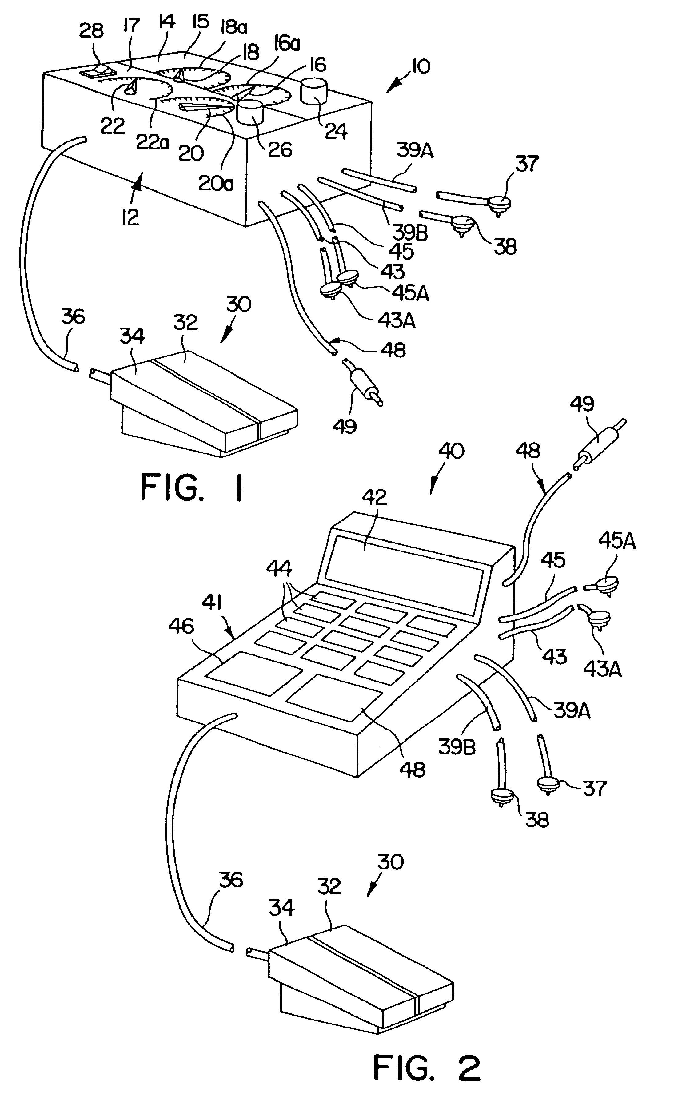
[0035]Referring, now to FIG. 1, a first embodiment of an electro-stimulation device 10 includes a housing 12 and a control panel 14 located on an upper surface of the housing 12. The control panel 14 is divided into a heart stimulation control area 15 and a heart destimulation control area 17. The stimulation control area 15 includes a rotary dial 16 and scale 16A for setting the amount of current that is passed to the 20 heart, and a rotary dial 18 and scale 18A for setting the duration or frequency of cycles that the current is passed to the heart to start the heart beating. Likewise, the destimulation control area 17 includes a rotary dial 20 and scale 20A for setting the amount of current that is passed to the heart, and a rotary dial 22 and scale 22A for setting the duration that the current is passed to the heart to stop the heart from beating. Controls for regulating pulse width, pulse voltage, pulse phases and / or burst duration may also be added. A normally open stimulation ...


PUM


Abstract

An electro-stimulation device includes a pair of electrodes for connection to at least one location in the body that affects or regulates the heartbeat. The electro-stimulation device both electrically arrests the heartbeat and stimulates the heartbeat. A pair of electrodes are provided for connection to at least one location in the body that affects or regulates the heartbeat. The pair of electrodes may be connected to an intravenous catheter for transvenous stimulation of the appropriate nerve. A first switch is connected between a power supply and the electrodes for selectively supplying current from the power supply to the electrodes to augment any natural stimuli to the heart and thereby stop the heart from beating. A second switch is connected between the power supply and the electrodes for selectively supplying current from the power supply to the electrodes to provide an artificial stimulus to initiate heartbeating. In another aspect, the invention is directed to a method for arresting the beat of a heart in a living body comprising the steps of connecting the pair of electrodes to at least one location in the body that affects or regulates the heartbeat and supplying an electrical current to the electrodes of sufficient amplitude and duration to arrest the heartbeat. The device may also serve to still the lungs by input to a respirator or by stimulation of the phrenic nerve during surgical procedures.

Description

[0001]This application is a continuation of application Ser. No. 09 / 897,630 filed Jul. 2, 2001, now U.S. Pat. No. 6,542,774, which is a continuation of application Ser. No. 09 / 433,323 filed Nov. 3, 1999, now U.S. Pat. No. 6,266,564 and reissue application Ser. No. 10 / 004,183, which is a continuation of application Ser. No. 09 / 070,506 filed Apr. 30, 1998, now U.S. Pat. No. 6,006,134 and reissue application Ser. No. 10 / 004,182, which is a continuation in part of application Ser. No. 08 / 640,013 filed Apr. 30, 1996, now abandoned.BACKGROUND OF THE INVENTION[0002]1. Field of the Invention[0003]This invention relates to methods and devices for controlling the operation of the human heart or other organs by means of electrical stimulation, and more particularly, to devices for electronically slowing or stopping the heart.[0004]2. Description of the Related Art[0005]In some surgical procedures, such as coronary bypass surgery, it is necessary to stop the heart from beating so that the surge...

Claims


Application Information

Patent Timeline
Patent Type & Authority Patents(United States)
IPC IPC(8): A61N1/36A61N1/38A61B17/00A61B17/02A61B17/34A61N1/05A61N1/362A61N1/39
CPCA61B17/3417A61N1/3962A61N1/056A61N1/36114A61N1/362A61B2017/00243A61B2017/00969A61B2017/0243A61B2017/3445A61N1/385A61B2017/3449A61N1/39622
Inventor HILL, MICHAEL R. S.JONKMAN, KENNETH R.
Owner MEDTRONIC INC
Why Eureka
Try Eureka