Method and device for processing slaughter products

Inactive Publication Date: 2005-06-28
STORK PMT
View PDF18 Cites 61 Cited by
  • Summary
  • Abstract
  • Description
  • Claims
  • Application Information

AI Technical Summary

Benefits of technology

[0019]the selection of a specific slaughter product for a filleting processing leads to a higher yield, and therefore a higher profit in the case of heavier slaughter products;
[0020]the working costs for obtaining a specific quantity of fillet are considerably lower for heavy slaughter products than for light slaughter products;
[0021]separating waste with a low health risk from waste with a high health risk

Problems solved by technology

Without recording said data, it would be impossible to obtain any additional added value

Method used


Image

  • Method and device for processing slaughter products
  • Method and device for processing slaughter products
  • Method and device for processing slaughter products

Examples


Example

[0079]In various Figures, the way in which stationary components of a device are secured in a frame or the like is not shown, for the sake of clarity.

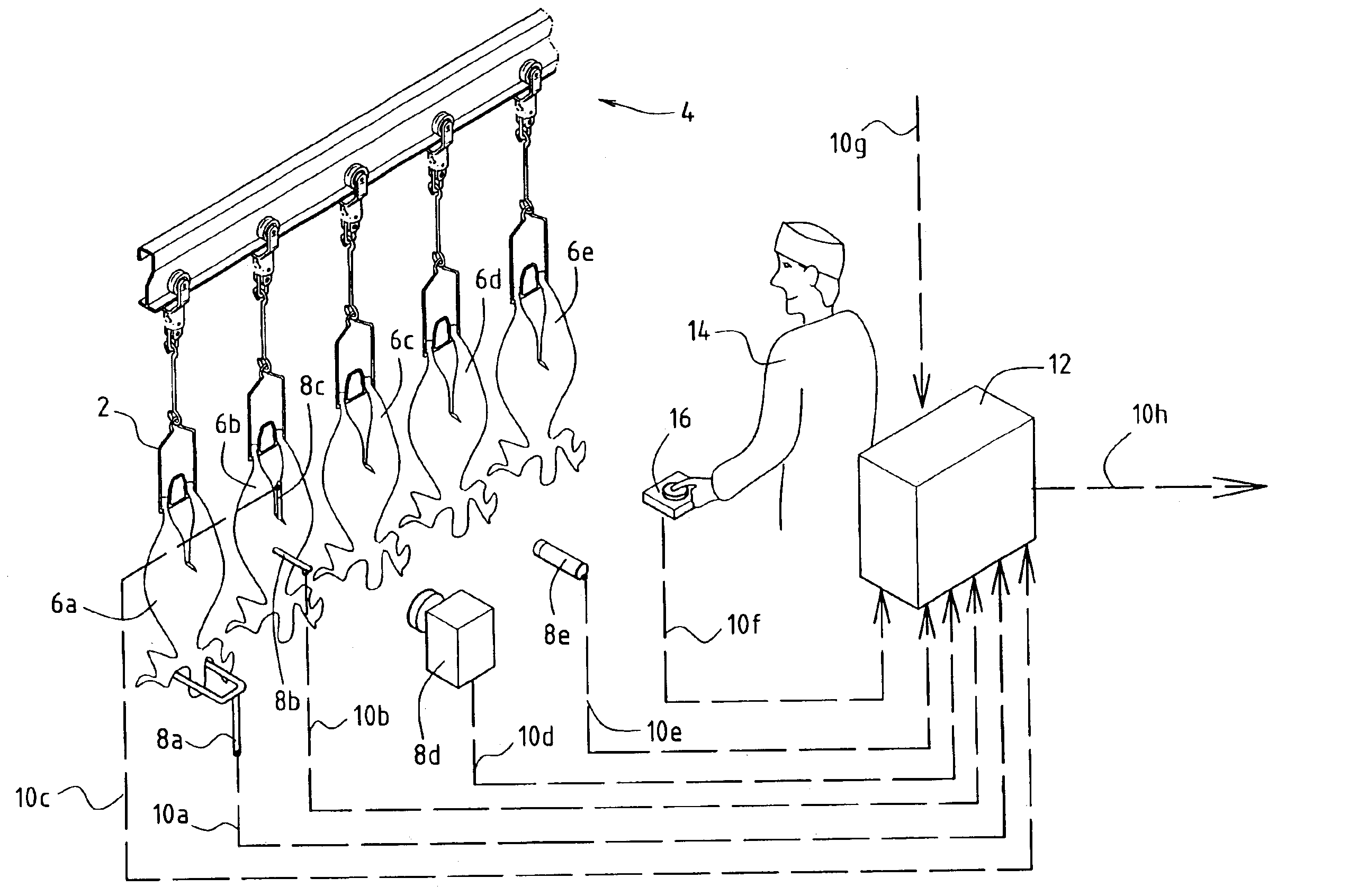
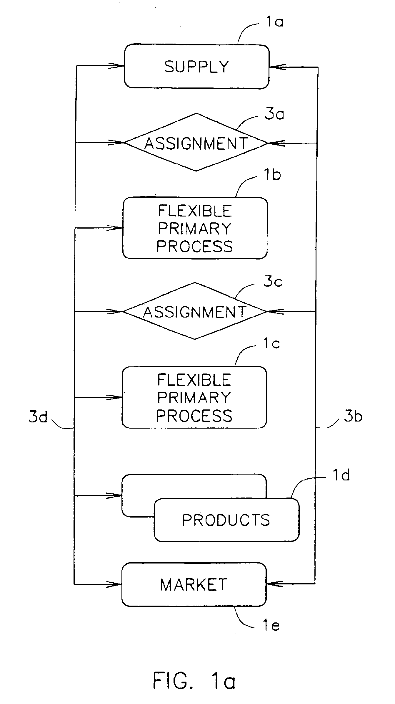
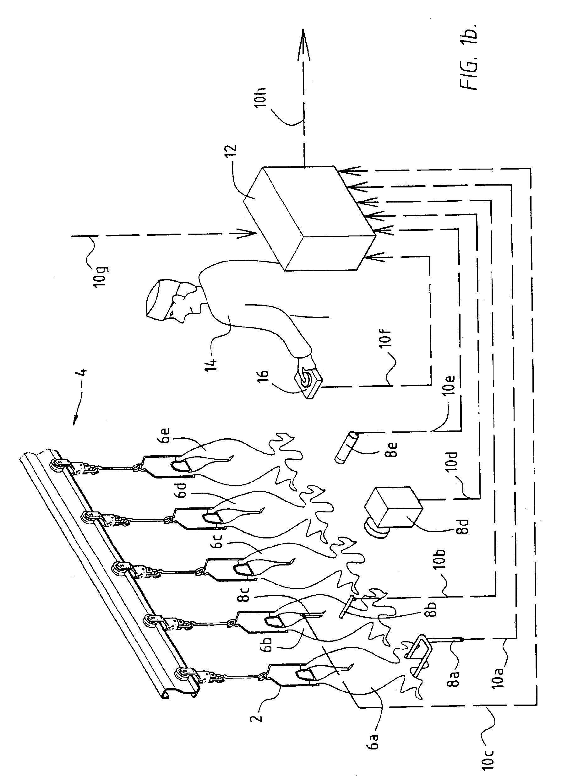
[0080]FIG. 1a shows processings in a meat-processing factory, in the form of a block diagram. Block 1a symbolizes the supply of slaughter animals from a fattening farm. Block 1b symbolizes flexible primary processings, such as slaughtering, removal of skin or feathers, exsanguination and removal of viscera. Block 1c symbolizes flexible secondary processings, such as boning, dividing, comminuting, marinating, crumb-coating, boiling, baking, frying and the like. Block 1d symbolizes the slaughter products obtained using the processings. Block 1e symbolizes the removal of the slaughter products to the market.

[0081]The slaughter animals supplied, on their basis of their properties, as are known from the fattening farm (supply side), on the basis of information from the primary and secondary processings, and / or on the basis of information fr...


PUM


Abstract

A processing of a first slaughter product to form a second slaughter product comprises: providing one or more processing stations, a parameter of a processing to be carried out in the processing stations being adjustable; collecting and storing data indicating the availability of the processing stations; collecting and storing data which indicate the availability of the first and/or second slaughter product; collecting and storing properties of the first and/or second slaughter product; storing relationships between the parameter of the processing and the properties of the first and/or second slaughter product. The processing of the first slaughter product to form the second slaughter product is controlled by adjusting the parameter of the processing on the basis of said data, properties and/or relationships, such that an additional added value is obtained during the processing of the first slaughter product to form the second slaughter product.

Description


Claims


Application Information

Patent Timeline
Owner STORK PMT
Why Eureka
Try Eureka