Decoding apparatus and decoding method

Inactive Publication Date: 2005-06-28
KK TOSHIBA
View PDF10 Cites 8 Cited by
  • Summary
  • Abstract
  • Description
  • Claims
  • Application Information

AI Technical Summary

Benefits of technology

[0008]In accordance with the purpose of the invention, as embodied and broadly described, the invention is directed to reduce the operation load and hardware scale of the decoding apparatus using mask symbols.

Problems solved by technology

However, the longer the minimum Euclidean distance, the lower the transmission rate or coding efficiency.
However, for (32, 10) Reed-Muller code, it is difficult to calculate the checksum to be determined for the majority decision.
However, calculating the correlation of all code words for a received coded signal, essentially, operation load is high in this method, increasing the hardware scale; therefore, this method is difficult to realize for (32, 10) Reed-Muller code.
As mentioned above, it has been difficult to realize the decoding apparatus for recently proposed Reed-Muller code containing mask symbols which is resistant to the error.

Method used


Image

  • Decoding apparatus and decoding method
  • Decoding apparatus and decoding method
  • Decoding apparatus and decoding method

Examples


first embodiment

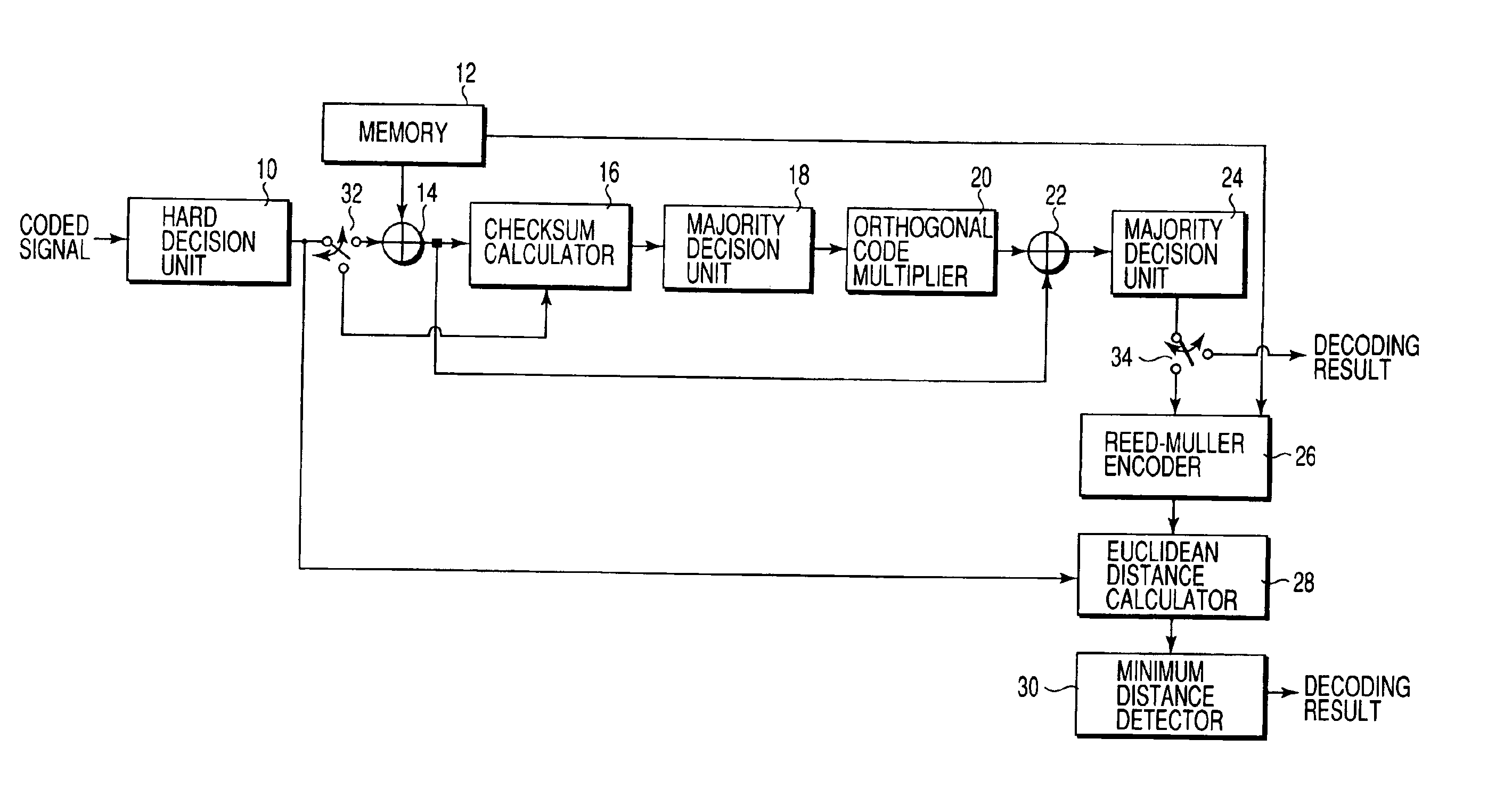
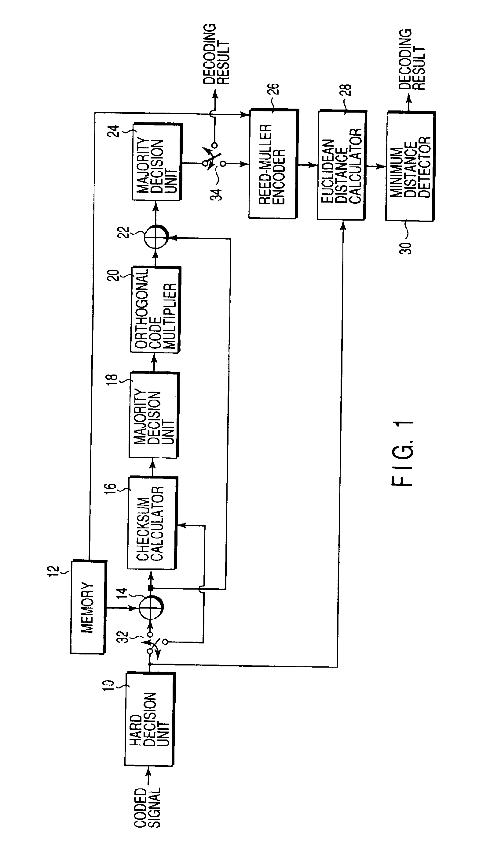
[0046]FIG. 1 shows a decoding apparatus of (32, 10) Reed-Muller code according to the first embodiment of the present invention. In (32, 10) Reed-Muller code, as the mask symbols are selected by 4-bit information data, patterns of the mask symbols (mask patterns) are 24=16 patterns in total.

[0047]The following definition will be used for the description below.

[0048]“^” means an exclusive OR operation. For two vectors, A and B, “A^B” represents the exclusive OR of components of respective vectors A and B.

[0049]m(A) represents the vector A in which each of components 0 and 1 is changed to +1 and −1.

[0050]10-bit information data to be encoded are assumed to be d0, d1, d2, d3, d4, d5, d6, d7, d8 and d9. Each bit data dn is 0 or 1.

[0051]Orthogonal codes used for encoding are assumed to be C0, C1, C2, C3, C4 and C5. Each code Cn is a 32-bit data, and 32 elements thereof are 0 or 1. Note that C0 is a series of all 1.

[0052]Similarly, assuming mask symbols used for encoding be M1, M2, M3 and...

second embodiment

[0096]FIG. 4 shows a second embodiment of the decoding apparatus which is simplifier than the first embodiment.

[0097]Comparing the output (expression (5)) of the exclusive OR circuit 22 and the Euclidean distance (expression (8)) between the output (expression (7)) of the Reed-Muller encoder 26 and the output (expression (2)) of the hard decision circuit 10, it is found that the expression (8) includes d0′C0 which is not included in the expression (5). If d0′=1, the expression (8) is an inversion of the expression (5) since C0 is a code of all 1.

[0098]Therefore, it can be determined that one of the output (expression (5)) of the exclusive OR circuit 22 and the inverted signal of the output of the exclusive OR circuit 22 which has the shorter Euclidean distance is a correct code. Thus, it is unnecessary to provide the majority decision unit 24, the Reed-Muller encoder 26, and the Euclidean distance calculator 28 of FIG. 1.

[0099]A result of accumulation of each bit of the expression (...

third embodiment

[0106]FIG. 6 shows a decoding apparatus of (32, 10) Reed-Muller code according to the third embodiment. Though the first and second embodiments relate to the hard decision, the third embodiment relates to a soft decision.

[0107]The following definition will be used for the description below.

[0108]“^” means an exclusive OR operation. For two vectors, A and B, “A^B” represents the exclusive OR of components of respective vectors A and B.

[0109]m(A) represents the vector A in which each of components 0 and 1 is changed to +1 and −1.

[0110]10-bit information data to be encoded are assumed to be d0, d1, d2, d3, d4, d5, d6, d7, d8 and d9. Each bit data dn is 0 or 1.

[0111]Orthogonal codes used for encoding are assumed to be C0, C1, C2, C3, C4 and C5. Each code Cn is a 32-bit data, and 32 elements thereof are 0 or 1. Note that C0 is a series of all 1.

[0112]Similarly, assuming mask symbols used for encoding be M1, M2, M3 and M4. Each mask symbol Mn is a 32-bit data. The mask patterns d6M1^d7M2^...


PUM


Abstract

Decoding apparatus comprises EX-OR circuit exclusive ORing the Reed-Muller code and exclusive Ored value of mask symbol candidate pattern and the information data corresponding to the pattern, first decoder calculating checksum of the EX-OR circuit output and majority-judging the checksum to decode a part of the second portion of the information data, second decoder exclusive ORing the EX-OR circuit output and a product of the part of the second portion and the orthogonal codes and majority-judging the exclusive OR result to decode a remaining part of the second portion, Reed-Muller encoder encoding the information data, and minimum detector detecting the minimum of Euclidean distance between an output from the Reed-Muller encoder and the Reed-Muller code supplied to the arithmetic operation unit while a plurality of candidate patterns of the mask symbols are supplied to the arithmetic operation unit.

Description

CROSS-REFERENCE TO RELATED APPLICATIONS[0001]This application is based upon and claims the benefit of priority from the prior Japanese Patent Applications No. 2000-092163, filed Mar. 29, 2000; and No. 2001-071358, filed Mar. 14, 2001, the entire contents of both of which are incorporated herein by reference.BACKGROUND OF THE INVENTION[0002]The present invention relates to Reed-Muller decoding apparatus and decoding method.[0003]Reed-Muller code is known as a kind of error correction code. An ordinary Reed-Muller code is (32, 6) Reed-Muller code for converting 6-bit information data into a 32-bit code word. For the Reed-Muller code, it is known that, suppose n=2m (n is a code length, m is a natural number (if n=32, m=5)), the minimum Euclidean distance between code words is 2m-r (r is an order of code). In general, if the minimum Euclidean distance between code words is longer, the error correction code has better performance (resistant to errors). However, the longer the minimum Euc...

Claims


Application Information

Patent Timeline
IPC IPC(8): H03M13/00H03M13/05H03M13/45H03M13/03H03M13/13
CPCH03M13/451H03M13/136H03M13/13H03M13/45
Inventor TAKEDA, DAISUKEMUKAI, MANABU
Owner KK TOSHIBA
Why Eureka
Try Eureka