Method of producing multilayer piezoelectric resonator

a piezoelectric resonator and multi-layer technology, applied in the direction of device details, device material selection, piezoelectric/electrostrictive device details, etc., can solve the problems of ceramic material diffraction during baking, metals such as ag-pd, used in the internal electrodes b>, etc., to reduce production costs, improve stacking precision, and prevent a reduction of difference f

Inactive Publication Date: 2005-07-05
MURATA MFG CO LTD
View PDF7 Cites 5 Cited by
  • Summary
  • Abstract
  • Description
  • Claims
  • Application Information

AI Technical Summary

Benefits of technology

[0011]In order to overcome the problems described above, preferred embodiments of the present invention provide a method of producing a multilayer piezoelectric resonator which makes it possible to prevent a reduction in a difference Δf between a resonant frequency and an antiresonant frequency by preventing diffusion of an internal electrode during baking, to reduce production costs by using one type of print pattern, and to increase stacking precision.
[0014]In one of the preferred embodiments of the present invention, electrodes are not printed after punching out portions of a green sheet with certain shapes as they are in the related example. Instead, after printing electrically conductive pastes onto the green sheet with the same forms, and forming the internal electrodes on the green sheet, portions of this green sheet are punched out with certain sizes. Here, with a particular position of each of the internal electrodes serving as a reference position, at least three types of sheets including a first green sheet, a second green sheet, and a green third sheet, are punched out from the green sheet having the internal electrodes formed thereon. The first green sheet is punched out by shifting a punching location by a first shift amount in a first direction with respect to the reference position, the second green sheet is punched out by shifting a punching location by the first shift amount in an opposite direction to the first direction, and the third green sheet is punched out at the reference position. The first and second green sheets are punched out by shifting the punching locations by the first shift amount from the reference position so that the internal electrodes formed at their surfaces are exposed at opposing end surfaces of the unit when a unit has been formed by cutting the layered body. The internal electrode formed at the third green sheet is such as not to be exposed at an end surface of the unit when a unit has been formed by cutting the layered body. In other words, the third green sheet is punched out so that the internal electrode becomes a float electrode. Since the punching-out operations are carried out with the electrode patterns as references, the precision with which the internal electrode and the outer periphery of each of the punched out green sheets are positioned with respect to each other is kept high, so that, by only placing the green sheets upon each other in the vertical direction at the time of stacking, the electrodes are placed upon each other with high positional precision. After forming a unit by cutting the layered body formed by placing the green sheets upon each other in this way, the unit is baked. Here, since the float electrodes are provided between the internal electrodes and at the outer sides of the unit, diffusion of metals of the internal electrodes in the ceramic is reliably prevented during the baking, so that it is possible to prevent a reduction in Δf. In addition, since only one type of print pattern needs to be used, the production process is greatly simplified, and the process from printing to punching to stacking can be carried out in one production line, thereby allowing for greatly reduced production costs.
[0016]Here, when a unit has been formed by cutting the layered body, the internal electrode formed at the surface of the first green sheet and the internal electrode formed at the surface of the second green sheet are exposed at adjacent end surfaces of the unit. The internal electrode formed at the third green sheet is not exposed at an end surface, so that it becomes a float electrode. In this way, even if one type of print pattern is used, by changing the shift direction during the punching-out operation, an end surface where an internal electrode is exposed can be arbitrarily changed, thereby providing the advantage of increased design freedom of the multilayer piezoelectric resonator.

Problems solved by technology

This type of piezoelectric resonator has a problem in that metals, such as Ag-Pd, used in the internal electrodes 33 diffuse in ceramic material during baking.
Consequently, there are disadvantages in that the production process becomes complicated and that costs are increased.
Therefore, positional displacements thereof during the printing directly affect the precision with which the electrodes are positioned.

Method used


Image

  • Method of producing multilayer piezoelectric resonator
  • Method of producing multilayer piezoelectric resonator
  • Method of producing multilayer piezoelectric resonator

Examples


Embodiment Construction

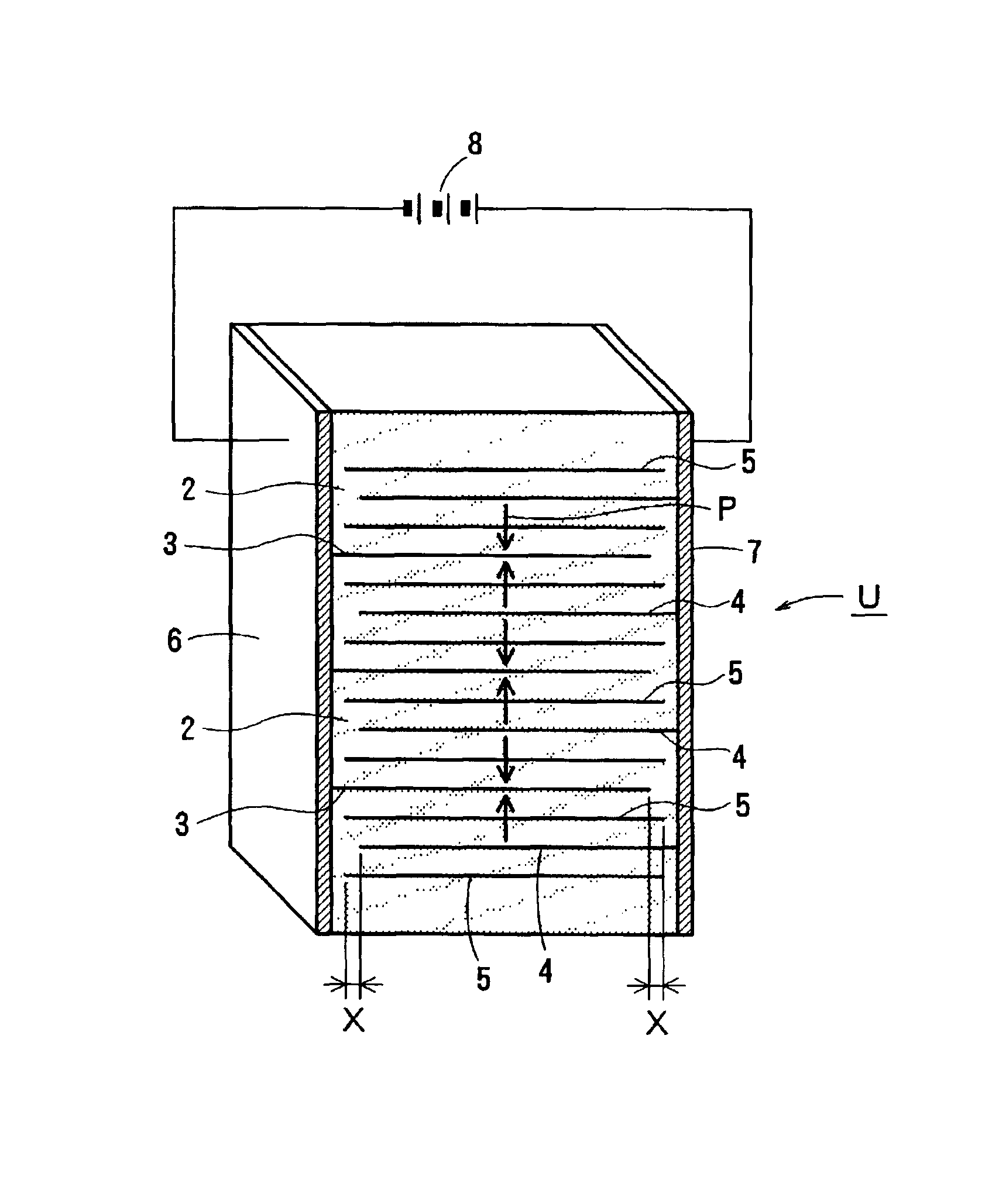
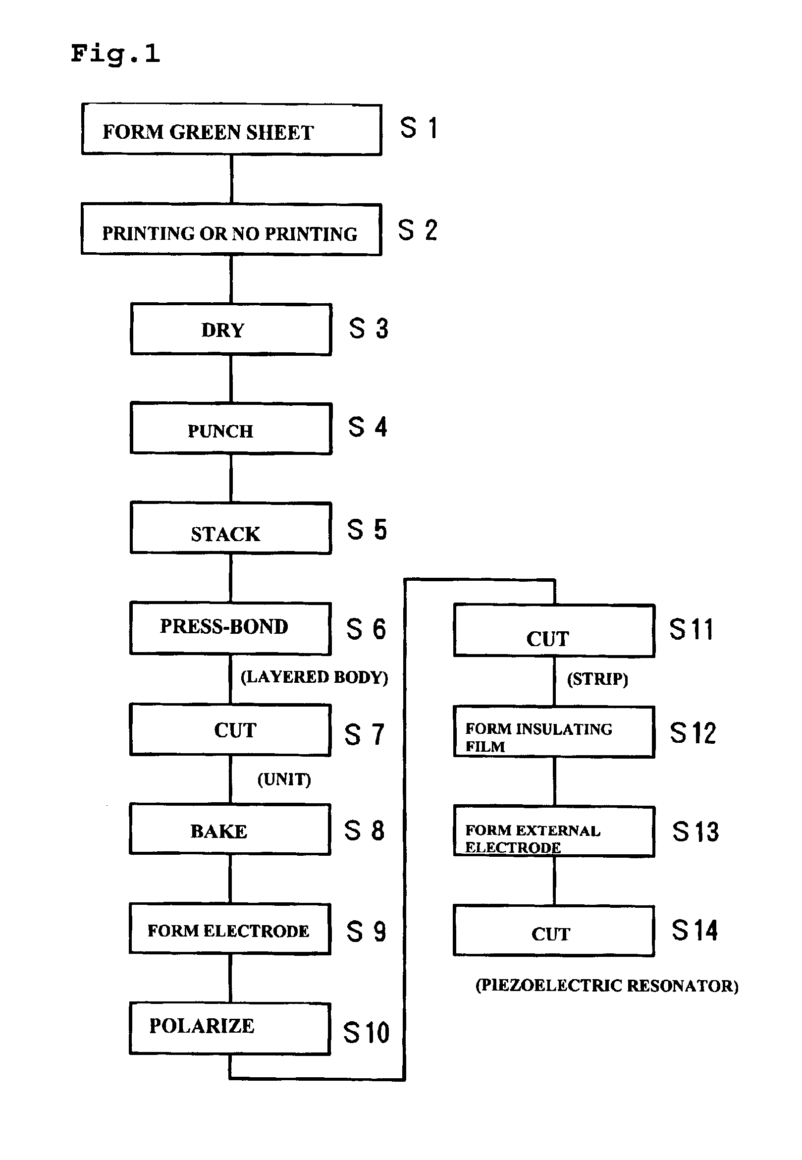
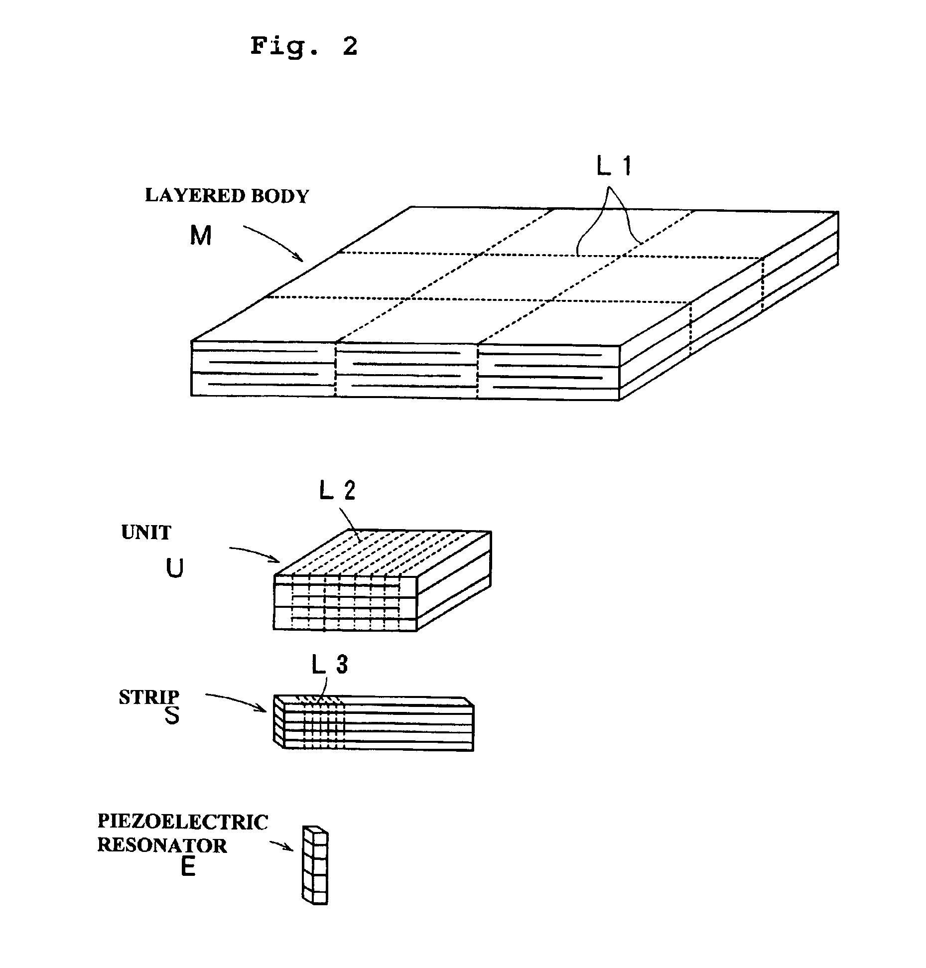
[0030]FIG. 1 is an overall flowchart of a method of producing a length mode multilayer piezoelectric resonator according to a preferred embodiment of the present invention. FIG. 2 illustrates the forms of a layered body M, a unit U, a strip S, and a device E in the process of producing the multilayer piezoelectric resonator.

[0031]First, in Step S1, a continuous green sheet is produced by forming a ceramic slurry into the form of a sheet. In Step S2, internal electrodes are printed onto some portions of the continuous green sheet, but not on other portions of the continuous green sheet. In Step S3, the internal electrodes are dried. Thereafter, in Step S4, portions of the continuous green sheet are punched out with certain shapes in order to form a plurality of green sheets. In Step S5, the plurality of green sheets are placed upon each other in a predetermined order, and, in Step S6, the plurality of green sheets are press-bonded together to form a layered body M. In Step S7, the la...


PUM

PropertyMeasurementUnit
thicknessaaaaaaaaaa
electrically conductiveaaaaaaaaaa
sizesaaaaaaaaaa

Abstract

A method of producing a piezoeIectric resonator includes the steps of forming first to third internal electrodes by printing an electrically conductive paste onto a green sheet, punching out portions of the green sheet having the first to third internal electrodes formed thereon, so that at least three types of green sheets are punched out with a location of the internal electrode serving as a reference location, in which the first sheet is punched out by shifting a punching location by a first shift amount in a first direction with respect to the reference location, the second sheet is punched out by shifting a punching location by the first shift amount in a direction opposite to the first direction, and the third sheet is punched out at the reference location, forming a layered body by stacking the punched out green sheets, and forming a unit by cutting the layered body.

Description

BACKGROUND OF THE INVENTION[0001]1. Field of the Invention[0002]The present invention relates to a method of producing a multilayer piezoelectric resonator for use in, for example, a filter for a cellular phone.[0003]2. Description of the Related Art[0004]A length mode piezoelectric resonator which has a high design freedom in terms of characteristics, which has little spurious, and which makes it possible to increase a difference Δf between a resonant frequency and an antiresonant frequency has been provided (for example, described in Japanese Unexamined Patent Application Publication No. 10-4330).[0005]FIG. 10 shows an example of a length mode piezoelectric resonator 30. The piezoelectric resonator 30 includes a substrate 31 having a plurality of piezoelectric layers 32 and a plurality of internal electrodes 33 alternately stacked upon each other, with the piezoelectric layers 32 at both sides of the corresponding internal electrodes 33 being polarized in opposite directions as in...

Claims


Application Information

Patent Timeline
Patent Type & Authority Patents(United States)
IPC IPC(8): H03H3/02H03H3/00H01L41/24H01L41/083H01L41/22H01L41/338H01L41/339
CPCH03H3/02H01L41/273H01L41/338Y10T29/49005Y10T29/42Y10T29/49798Y10T29/49155Y10T29/49126Y10T29/49128Y10T29/49789H10N30/053H10N30/088
Inventor YASUGI, TOSHIYUKIFUJINO, YUJIKAWABATA, SHOICHIOGAWA, MAMORU
Owner MURATA MFG CO LTD
Why Eureka
Try Eureka