Piezoelectric fuel injection system with rate shape control and method of controlling same

a fuel injection system and rate shape technology, applied in the direction of electrical control, process and machine control, etc., can solve the problems of increasing the control volume pressure, closing the needle valve, and reference does not provide a solution for effective control of the rate shape of the fuel injection, so as to reduce exhaust emissions and improve fuel economy

Active Publication Date: 2005-07-05
CUMMINS INC
View PDF21 Cites 59 Cited by
  • Summary
  • Abstract
  • Description
  • Claims
  • Application Information

AI Technical Summary

Benefits of technology

[0011]In view of the foregoing, an aspect of the present invention is a piezoelectric

Problems solved by technology

Opening of the injection control valve causes a reduction in the fuel pressure in the control volume resulting in a pressure differential which forces the needle valve open, and closing of the injection control valve causes an increase in the control volume pressure and closing of the needle valve.
Although the above described reference provides some control over fuel metering, and thus, control over the amount of fuel injected, the reference does not provide a solution for effectively co

Method used


Image

  • Piezoelectric fuel injection system with rate shape control and method of controlling same
  • Piezoelectric fuel injection system with rate shape control and method of controlling same
  • Piezoelectric fuel injection system with rate shape control and method of controlling same

Examples


Embodiment Construction

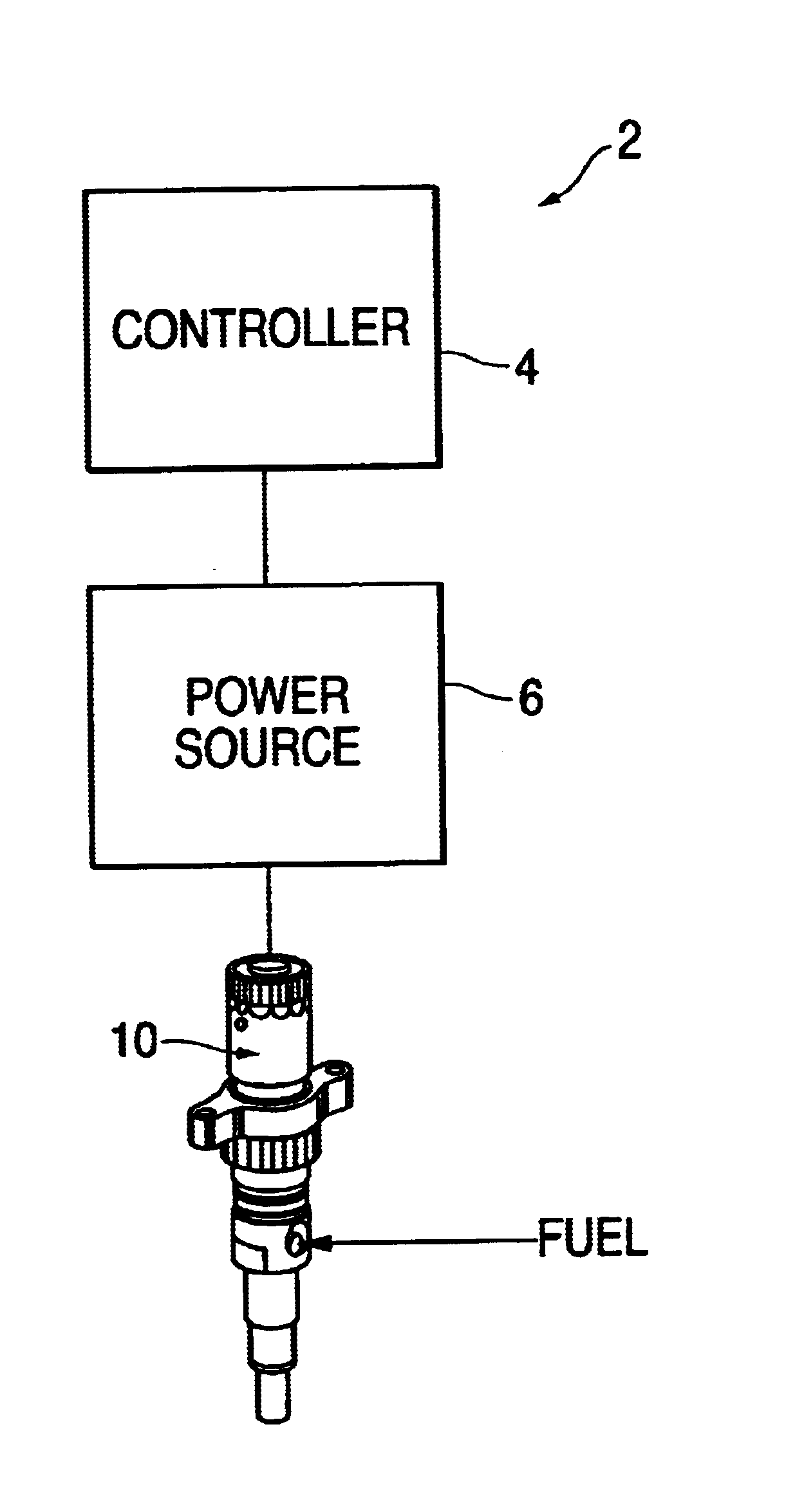
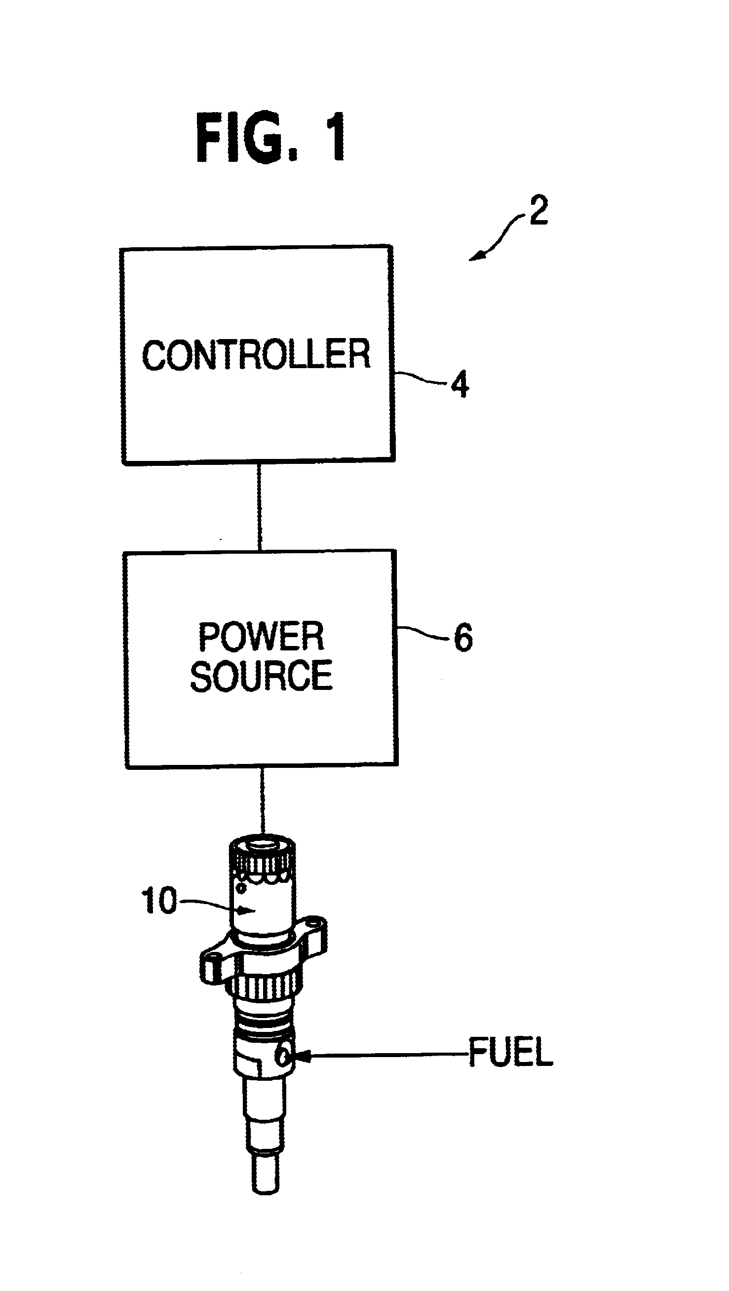
[0029]FIG. 1 shows a schematic illustration of a piezoelectric fuel injection system 2 in accordance with one embodiment of the present invention that avoids the above noted limitations of conventional fuel injection systems. As described in further detail below, the piezoelectric fuel injection system 2 allows enhanced control of the rate of fuel injected during an injection event of a combustion cycle in an internal combustion engine, for example, a diesel engine, so that the rate shape can be effectively controlled. Of course, the present invention may also be applied to other types of internal combustions as well.

[0030]The piezoelectric fuel injection system 2 of the illustrated embodiment includes a controller 4 that is connected to a power source 6, the controller 4 being adapted to control the power source 6. The power source 6 of the piezoelectric fuel injection system 2 is connected to a fuel injector 10 and provides power thereto in the manner as further described below in...


PUM


Abstract

A piezoelectric fuel injection system and a method of controlling same, the system including a piezoelectric fuel injector having a piezoelectric element, a power source adapted to provide power to the piezoelectric element to actuate the piezoelectric fuel injector, and a controller adapted to cyclically modulate power provide to the piezoelectric element by the power source during at least a portion of the injection event. The controller cyclically modulates the power between a predetermined first voltage and a predetermined second voltage that is less than the first voltage to control the rate of fuel injected by the piezoelectric fuel injector during the portion of the injection.

Description

BACKGROUND OF THE INVENTION[0001]1. Field of the Invention[0002]The present invention is directed to piezoelectric injection systems having a mechanism for controlling rate shape, and to methods for controlling such piezoelectric injection systems.[0003]2. Description of Related Art[0004]In most fuel supply systems applicable to internal combustion engines, fuel injectors are used to inject fuel pulses into the engine combustion chamber. A commonly used injector is a closed-nozzle injector which includes a nozzle assembly having a spring-biased nozzle valve element positioned adjacent the nozzle orifice for allowing fuel to be injected into the cylinder. The nozzle valve element also functions to provide a deliberate, abrupt end to fuel injection thereby preventing a secondary injection which causes unburned hydrocarbons in the exhaust. The nozzle valve is positioned in a nozzle cavity and biased by a nozzle spring so that when the pressure of the fuel within the nozzle cavity excee...

Claims


Application Information

Patent Timeline
IPC IPC(8): F02M51/06F02D41/20
CPCF02D41/2096F02M51/0603F02D2041/2027F02D2041/2034
Inventor RAUZNITZ, PETERCROFTS, JOHN D.PETERS, LESTER L.
Owner CUMMINS INC
Why Eureka
Try Eureka