Electro-optical device
a liquid crystal display and active matrix technology, applied in the direction of optical elements, identification means, instruments, etc., can solve the problems of reducing the aperture ratio, the gate bus line has not been able to provide a sufficient capacity by itself, and the pixel electrode portion is too small to store necessary electrical charge for a sufficient period of time, etc., to achieve stable operation, improve the effect of shading and advantageous operation of transistors
- Summary
- Abstract
- Description
- Claims
- Application Information
AI Technical Summary
Benefits of technology
Problems solved by technology
Method used
Image
Examples
first embodiment
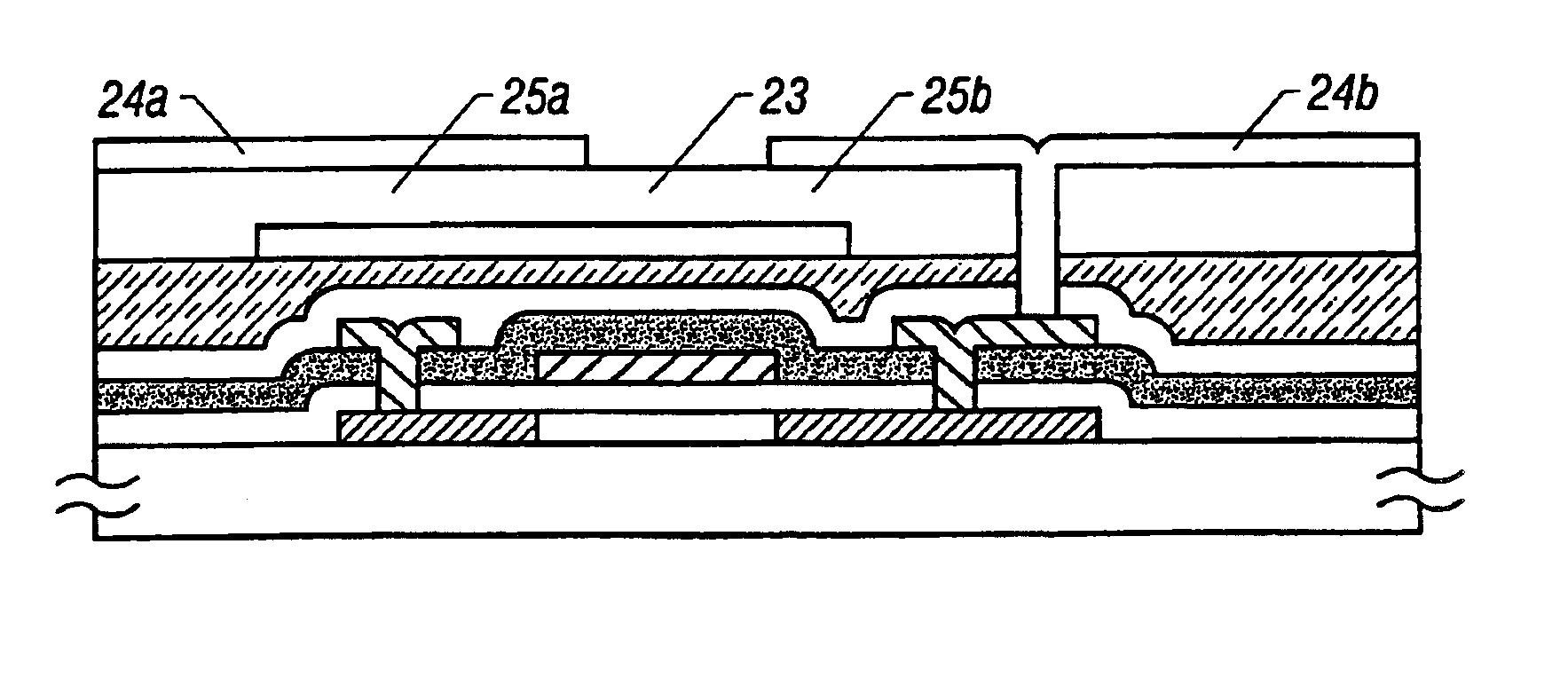
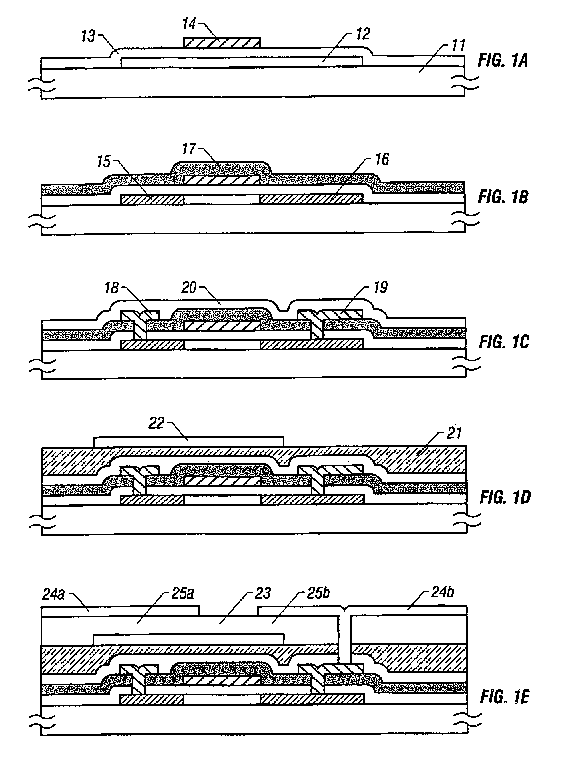
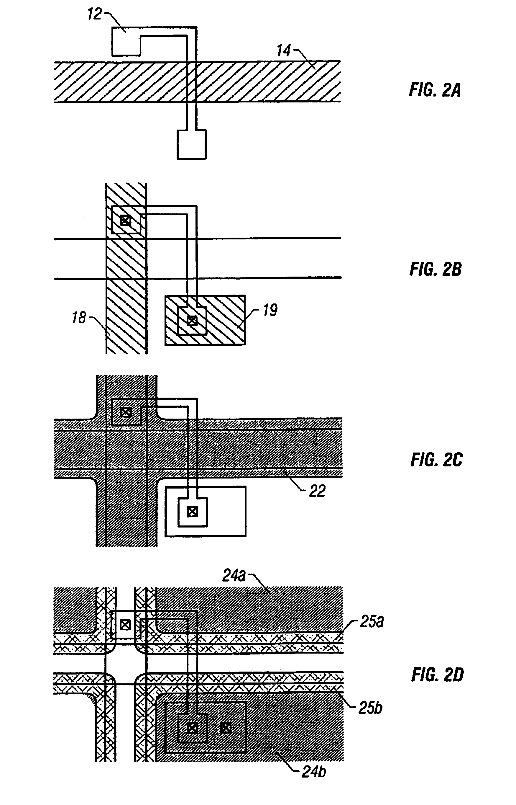
[0030]the present invention will now be described. FIGS. 1A through 1E and FIGS. 2A through 2D show a configuration of a pixel of an active matrix type liquid crystal display which employs the invention disclosed in this specification. FIGS. 1A through 1E are schematic sectional views showing fabrication steps according to the present embodiment, and FIGS. 2A through 2D show the configuration of each of a bus line, a common electrode, pixel electrodes, a semiconductor layer, and the like according to the present embodiment. The reference numbers in FIGS. 2A through 2D are in correspondence with those in FIGS. 1A through 1E. FIGS. 1A through 1E are conceptual views and are not exactly identical to FIGS. 2A through 2D in configuration.
[0031]Further, FIGS. 1A through 1E and FIGS. 2A though 2D show a configuration of only a substrate on which a thin film transistor is provided. In practice, there is provided another substrate opposite thereto (opposite substrate), and liquid crystal is ...
second embodiment
[0045]the present invention will now be described. FIGS. 3A through 3E and FIGS. 4A through 4D show a configuration of a pixel of an active matrix type liquid crystal display which employs the invention disclosed in this specification. FIGS. 3A through 3E are schematic sectional views showing fabrication steps according to the present embodiment, and FIGS. 4A through 4D show the configuration of each of a bus line, a common electrode, pixel electrodes, a semiconductor layer, and the like according to the present embodiment. The reference numbers in FIGS. 4A through 4D are in correspondence with those in FIGS. 3A through 3E. FIGS. 3A through 3E are conceptual views and are not exactly identical to FIGS. 4A through 4D in configuration.
[0046]As shown in FIG. 3A, a semiconductor layer (active layer) 32 of a transistor is provided on a glass substrate 31 having an underlying silicon oxide film (not shown). A gate insulation film 33 is formed so as to cover the active layer 32. A gate bus...
PUM
| Property | Measurement | Unit |
|---|---|---|
| insulating | aaaaa | aaaaa |
| leak current | aaaaa | aaaaa |
| electrical charge | aaaaa | aaaaa |
Abstract
Description
Claims
Application Information
 - R&D
- Intellectual Property
- Life Sciences
- Materials
- Tech Scout
- Unparalleled Data Quality
- Higher Quality Content
- 60% Fewer Hallucinations
Browse by: Latest US Patents, China's latest patents, Technical Efficacy Thesaurus, Application Domain, Technology Topic, Popular Technical Reports.
© 2025 PatSnap. All rights reserved.Legal|Privacy policy|Modern Slavery Act Transparency Statement|Sitemap|About US| Contact US: help@patsnap.com


