MR imaging system and data acquisition method

a data acquisition and imaging system technology, applied in the field of magnetic resonance imaging, can solve the problem of limited scanning time and achieve the effect of high temporal resolution

Inactive Publication Date: 2005-07-05
TOSHIBA MEDICAL SYST CORP
View PDF9 Cites 20 Cited by
  • Summary
  • Abstract
  • Description
  • Claims
  • Application Information

AI Technical Summary

Benefits of technology

[0019]Still, as another aspect of the present invention, there is provided a program installed in a magnetic resonance imaging system and executed by a computer of the magnetic resonance imaging system in order to acquire data from an object to be imaged using a pulse sequence formed to include a pre-pulse, an RF excitation pulse, an encoding gradient pulse, and a reading gradient pulse, the acquired data being in a k-space, wherein the pulse sequence is formed such that the encoding gradient pulse has an encoding amount determined to allow a data acquisition position in the k-space to be directed outward from a center of the k-space, a train of pulses including the RF excitation pulse, the encoding gradient pulse, and the reading gradient pulse is repeated to allow the number of times of data acquisition in the k-space to become larger as approaching to a central region of the k-space, and The pre-pulse is formed to be reduced in an application rate to the RF excitation pulse as approaching to an outward position in the k-space.

Problems solved by technology

Therefore, even for conducting three-dimensional contrast enhanced MRA, the scan time can be limited to a period of time falling a usual patient's one-time breath hold

Method used


Image

  • MR imaging system and data acquisition method
  • MR imaging system and data acquisition method
  • MR imaging system and data acquisition method

Examples


Embodiment Construction

[0027]Hereinafter, with reference to FIGS. 1 to 5, an embodiment of the present invention will now be described.

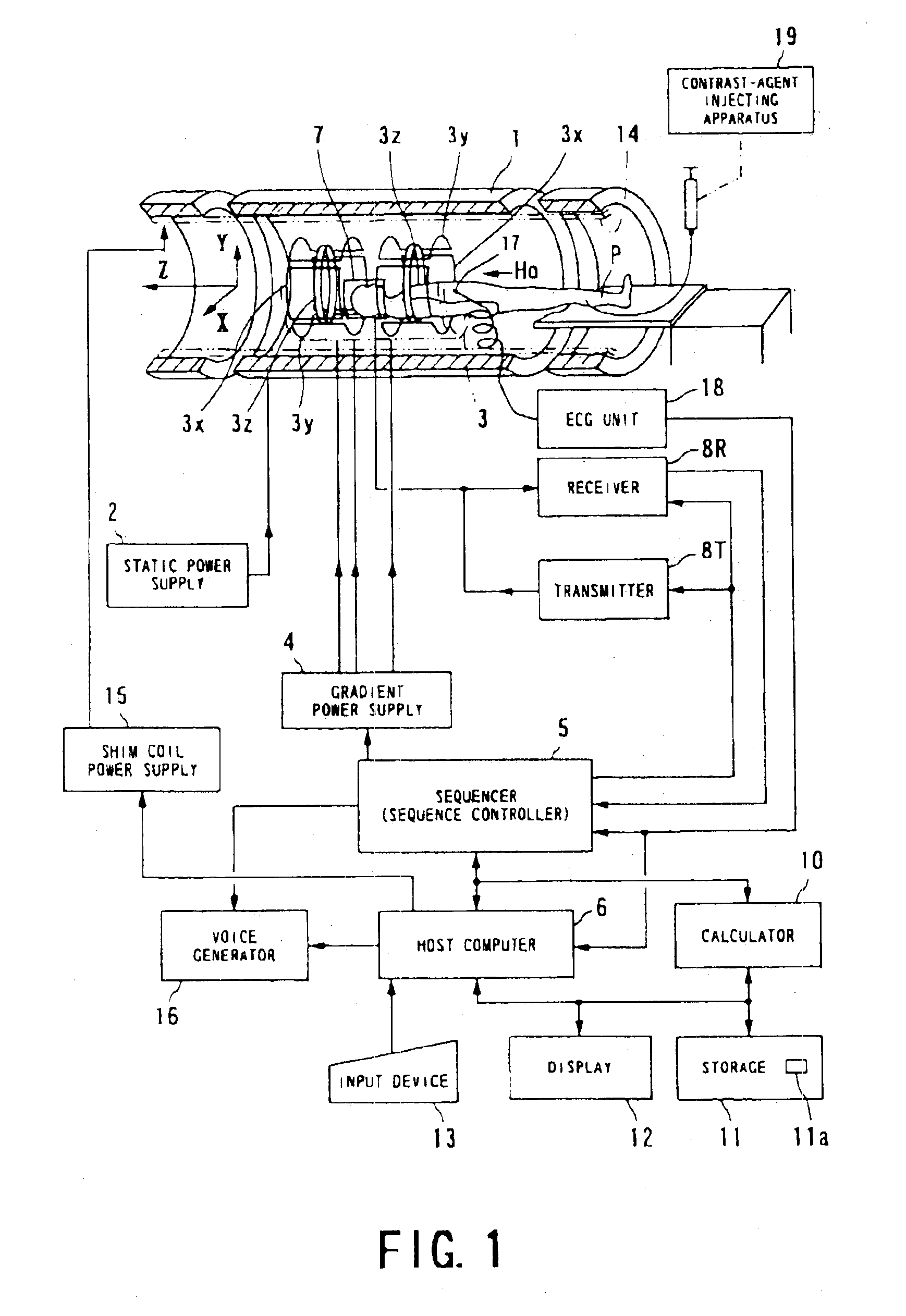
[0028]A magnetic resonance imaging (MRI) system used in this embodiment is outlined in FIG. 1.

[0029]The magnetic resonance imaging system comprises a patient couch on which a patient (object to be examined) P lies down on its couch top, static field generating components for generating a static magnetic field, gradient generating components for appending positional information to the static magnetic field, transmitting / receiving components for transmitting and receiving radio-frequency signals, controlling and calculating components responsible for control of the whole system and reconstruction of images, electrocardiographing components for acquiring an ECG signal which is a representative signal indicative of the cardiac temporal phase of a patient, and breath-hold instructing components for instructing the patient to temporarily hold his or her breath.

[0030]The static f...


PUM


Abstract

Magnetic resonance imaging uses a pulse sequence formed to include a pre-pulse, an RF excitation pulse, an encoding gradient pulse, and a reading gradient pulse. The encoding gradient pulse has an encoding amount determined to allow a data acquisition position in a k-space to be directed outward from a center of the k-space. A train of pulses including the RF excitation pulse, the encoding gradient pulse, and the reading gradient pulse is repeated to allow the number of times of data acquisition in the k-space to become larger as approaching to a central region of the k-space. The pre-pulse is formed to be reduced in an application rate to the RF excitation pulse as approaching to an outward position in the k-space. By way of example, this pulse sequence is used for contrast enhanced MRA carried out under a dynamic scan.

Description

BACKGROUND OF THE INVENTION[0001]1. Technical Field of the Invention[0002]The present invention relates to magnetic resonance imaging based on a magnetic resonance phenomenon in an object to be examined to obtain images of the object, and in particular, to the magnetic resonance imaging designed to perform a pulse sequence based on an encoding technique known as “Elliptic Centric (or Swirl)” preferable to contrast enhanced MRA (Magnetic Resonance Angiography) adopting a dynamic scan performed with an MR (Magnetic Resonance) contrast agent injected into the object.[0003]2. Description of Prior Art[0004]Magnetic resonance imaging is based on a technique that magnetically excites nuclear spins in an object placed in a static magnetic field with an RF signal of a Larmor frequency of the nuclear spins, acquires an MR signal emanated from the object due to the excitation, and reconstructs an image using the MR signal.[0005]In order to perform this magnetic resonance imaging, it is require...

Claims


Application Information

Patent Timeline
Patent Type & Authority Patents(United States)
IPC IPC(8): G01R33/563G01R33/54G01R33/561G01R33/28A61B5/055G01R33/48
CPCG01R33/563G01R33/281G01R33/5611G01R33/56308
Inventor OOKAWA, MASASHI
Owner TOSHIBA MEDICAL SYST CORP
Why Eureka
Try Eureka