
Micro mirror unit, optical disc drive using same, and method for producing micro mirror unit

a micro-mirror and optical disc technology, applied in the direction of originals for photomechanical treatment, disposition/mounting of heads, instruments, etc., can solve the problems of poor efficiency, increased cost, and possible damage to the hinge, and achieve the effect of shortening the time, reducing the cost of etching, and high precision

Inactive Publication Date: 2005-07-05
SONY CORP
View PDF9 Cites 21 Cited by
  • Summary
  • Abstract
  • Description
  • Claims
  • Application Information

AI Technical Summary

Benefits of technology

[0016]It is therefore an object of the present invention to overcome the above-mentioned drawbacks of the prior art by providing a micro mirror unit whose hinge is resistant against pivoting of a mirror body for effective prevention thereof from being damaged and can be formed finely and with a high precision and which has such a structure as can be produced easily in a short time, an optical disc drive using the micro mirror unit, and a method for producing the micro mirror unit.

Problems solved by technology

However, since the micro mirror unit is adapted for the mirror body thereof to be pivotable about the hinge to a tilted position in a selected direction, the hinge will possibly be damaged due to a so-called metal fatigue as the mirror body is repeatedly pivoted.
In the micro mirror unit constructed as in the above, however, since the hinge is formed from the Si substrate material forming the frame as in the above, the shape of the hinge is limited to the thickness of the Si substrate material.
Also, since the micro working by the wet etching takes a very long time, the micro mirror unit having the frame, mirror substrate and hinge formed by the wet etching will be produced with a poor efficiency and with an increased cost.
Further, in the micro mirror unit, since the hinge is formed by micro working of the single Si substrate material by the wet etching, it cannot easily be formed more finely and with a high precision.
That is, in case the hinge is formed by the wet etching, the hinge having desired micro dimensions cannot be formed with a high precision because of the limited precision of the wet etching in the micro working.

Method used


Image

  • Micro mirror unit, optical disc drive using same, and method for producing micro mirror unit
  • Micro mirror unit, optical disc drive using same, and method for producing micro mirror unit
  • Micro mirror unit, optical disc drive using same, and method for producing micro mirror unit

Examples


Embodiment Construction

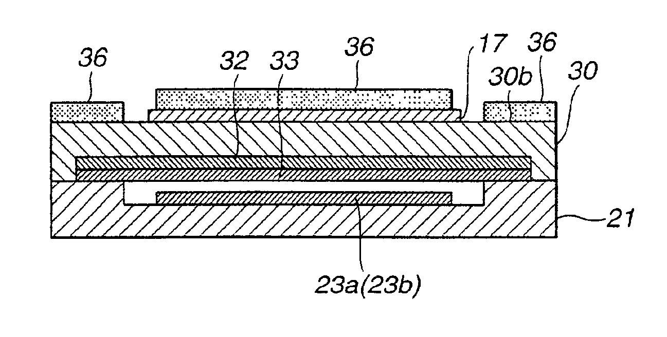
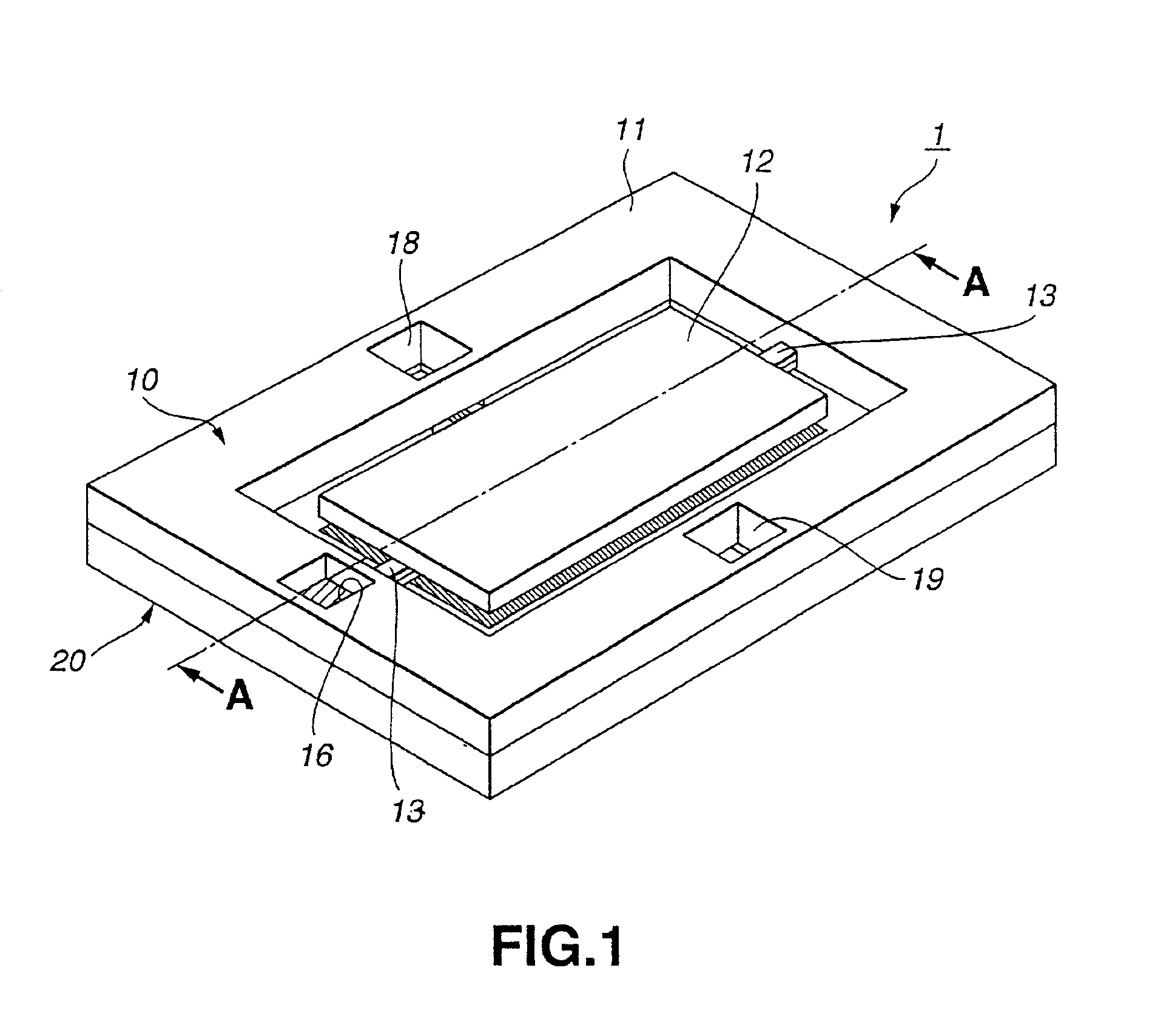
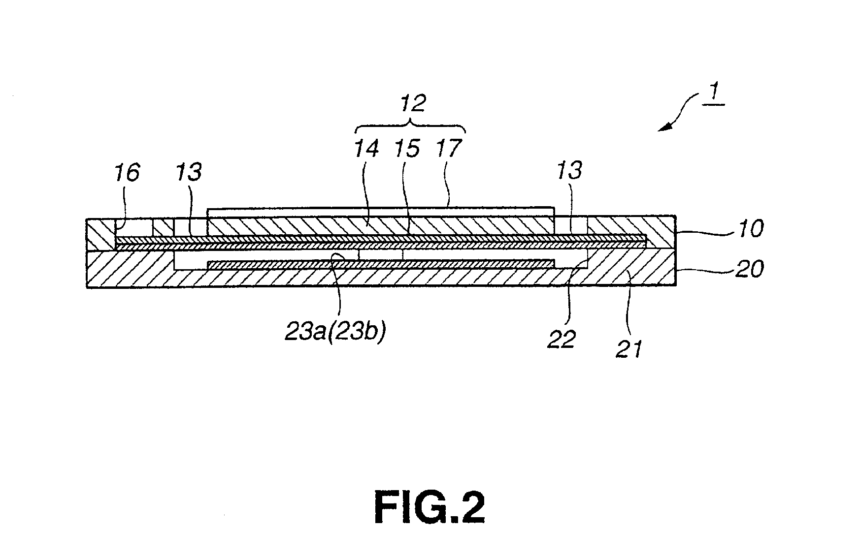
[0063]Referring now to FIGS. 1 to 3, there is schematically illustrated an embodiment of the micro mirror unit according to the present invention. The micro mirror unit is generally indicated with a reference 1, and it includes a first block 10 and second block 20, which are joined to each other by the anode bonding method or the like.

[0064]The fist block 10 includes a frame 11 formed from an Si substrate material to have the form of a ring opened at the center thereof by the dry etching, a mirror body 12 disposed in the central opening of the frame 11, and hinges 13 coupling the frame 11 and mirror body 12 to each other.

[0065]The mirror body 12 includes a mirror substrate 14 formed from the same Si substrate material as for the hinges 13 to have a predetermined form. That is, the mirror substrate 14 and frame 11 are formed from the single Si substrate material by the dry etching, and the central portion of the Si substrate material separated by the dry etching is used as the mirror...


PUM

PropertyMeasurementUnit
Ratioaaaaaaaaaa

Abstract

The hinge (13) should preferably be formed to have a higher resistance than ever against the pivoting of the mirror body (12) to effectively prevent the hinge (13) from being damaged. By adopting a suitable one of a variety of production steps as necessary, the hinge (13) can be formed more finely and with a higher precision and thus the micro mirror unit can be produced more easily in a shorter time. To this end, the hinge (13) is formed from a different material, such as SiNx, from the mirror substrate material from which the frame (11) and mirror body (12) are formed.

Description

RELATED APPLICATION DATA[0001]The present application claims priority to Japanese Application No. P11-375337 filed Dec. 28, 1999, which application is incorporated herein by reference to the extent permitted by law.BACKGROUND OF THE INVENTION[0002]1. Field of the Invention[0003]The present invention relates to a micro mirror unit in which a micro mirror can be moved electrostatically, an optical disc drive using the micro mirror unit, and a method for producing the micro mirror unit.[0004]2. Description of the Related Art[0005]In the recent electro-mechanical field of industry, the techniques in the semiconductor producing processes, etc. are utilized to actively develop techniques called “MEMS (micro electro-mechanical system)” intended for providing a variety of micro mechanical elements. A mirror designed with such MEMS techniques to be extremely compact as a light reflecting mechanical element is called “micro mirror unit”.[0006]The micro mirror unit consists of a frame and a mi...

Claims


Application Information

Patent Timeline
IPC IPC(8): B81B3/00B81C1/00G02B26/08G02B7/182G11B7/085G11B7/09G11B7/135
CPCB81C1/00595G02B26/0841G11B7/08564G02B7/1821B81B2201/042B81B2201/11B81B2203/0109Y10T428/24942G11B7/08576
Inventor HARA, MASAKIHORI, KAZUHITOIDO, HIROTOKOJIMA, NAOTOHANE, KAZUHIRO
Owner SONY CORP
Features
  • Generate Ideas
  • Intellectual Property
  • Life Sciences
  • Materials
  • Tech Scout
  • Unparalleled Data Quality
  • Higher Quality Content
  • 60% Fewer Hallucinations
Learn More