

Device and method for calibration of a microphone
- Summary
- Abstract
- Description
- Claims
- Application Information
AI Technical Summary
Benefits of technology
Problems solved by technology
Method used
Image

Examples
Embodiment Construction
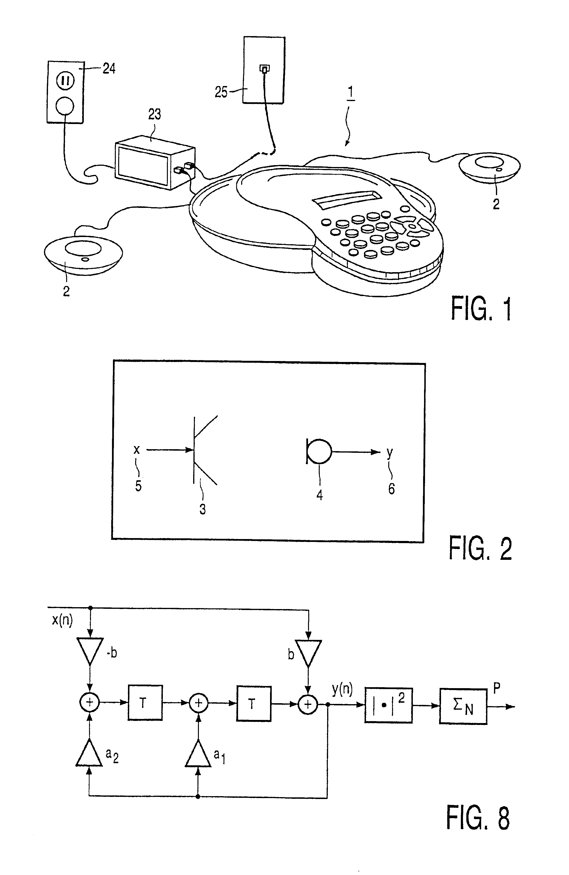
[0028]FIG. 1 shows an audio conferencing system comprising a main console 1 and one or two satellite microphones 2 for a larger pick-up range of speech, each satellite microphone containing a microphone. The audio conferencing system is connected to a floor unit 23, which, in turn, is connected to a power source 24 and a telephone network 25 of some kind, e.g., a PSTN (RJ11) or an ISDN (RJ45). The main console comprises, a loudspeaker for producing (voice) sounds, and three microphones for picking up (voice) sound. Furthermore, telephone means are included for making contact to other telephones through a telephone network. The microphones preferably inter-operate as seamlessly as possible. For this purpose, the invention provides means of eliminating the need of pre-installation calibration of the microphones in the satellite microphones or even of the microphones in the main console.
[0029]Another example of use of a device according to present invention (not shown), relates to voic...
PUM
 Abstract
Description
Claims
Application Information