Methods and apparatus for fabricating turbine engine airfoils

a technology for turbine engines and airfoils, which is applied in the field of turbine blades, can solve the problems that the small diameter rod may not provide enough structural support to the core, and achieve the effect of supporting the structural core of the casting cor

Inactive Publication Date: 2005-07-12
GENERAL ELECTRIC CO
View PDF13 Cites 21 Cited by
  • Summary
  • Abstract
  • Description
  • Claims
  • Application Information

AI Technical Summary

Benefits of technology

[0005]In one aspect of the invention, a method for casting an airfoil for a turbine engine is provided. The method includes forming a casting core to define a hollow portion in the airfoil and forming a print ou

Problems solved by technology

However, as an overall size and/or weight of the casting is increased, a s

Method used


Image

  • Methods and apparatus for fabricating turbine engine airfoils
  • Methods and apparatus for fabricating turbine engine airfoils
  • Methods and apparatus for fabricating turbine engine airfoils

Examples


Embodiment Construction

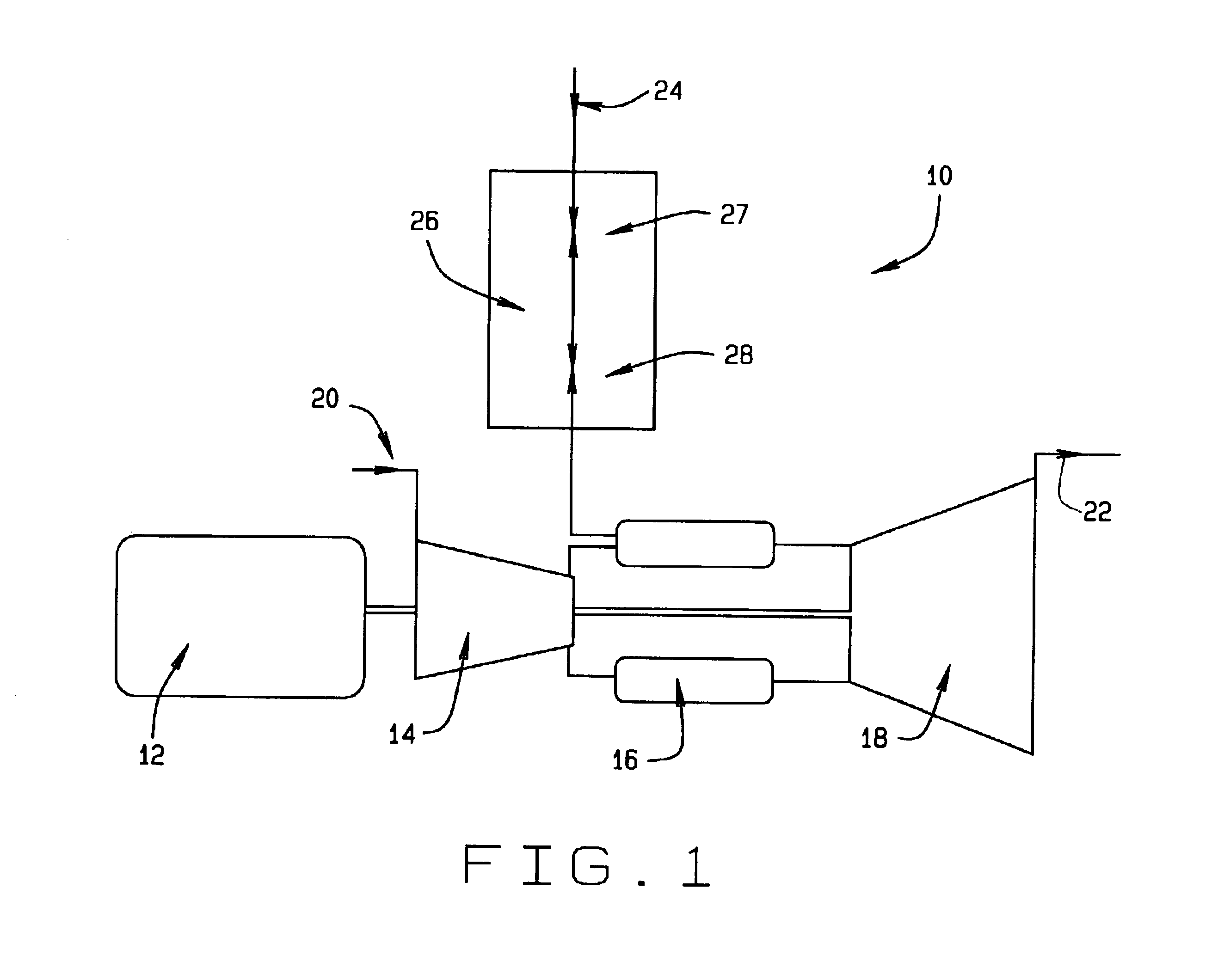
[0012]FIG. 1 is a schematic illustration of a gas turbine engine 10 including a generator 12, a compressor 14, a combustor 16 and a turbine 18. Engine 10 has an inlet or upstream side 20, an exhaust or downstream side 22, and a gas fuel inlet 24. The gas fuel passes through a gas control module 26 containing an isolation valve 27, known as the stop-ratio valve (SRV) and a gas control valve (GCV) 28. In one embodiment, engine 10 is a turbine engine commercially available from General Electric Power Systems, Schenectady, N.Y.

[0013]In operation, highly compressed air is delivered from compressor 14 to combustor 16. Gas fuel is delivered to the combustor 16 through a plurality of fuel nozzles (not shown in FIG. 1) and hot exhaust gas from combustor 16 is discharged through a turbine nozzle assembly (not shown in FIG. 1) and is used to drive turbine 18. Turbine 18, in turn, drives compressor 14 and generator 12.

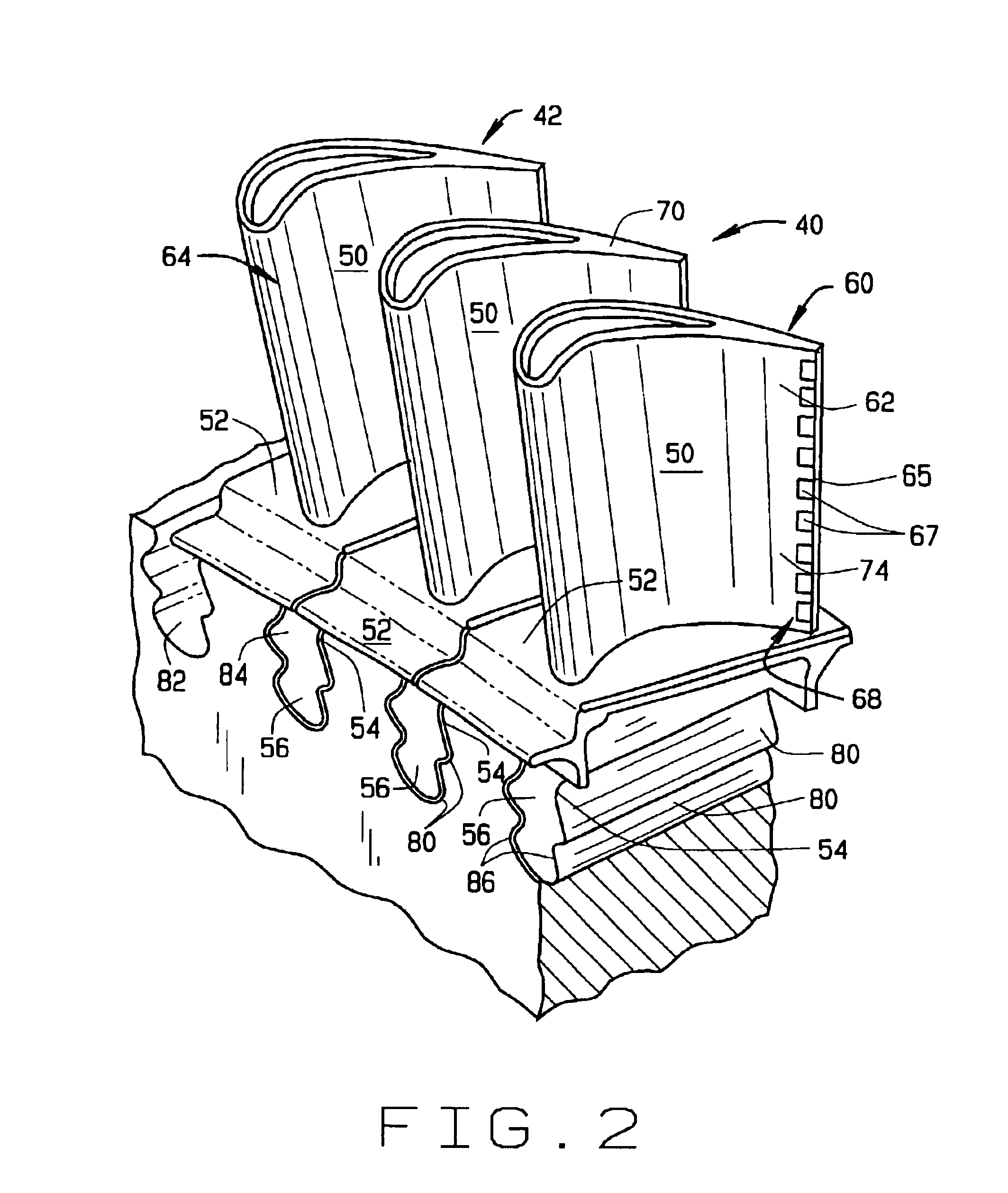
[0014]FIG. 2 is a perspective view of a rotor assembly 40 that may be used wi...


PUM

PropertyMeasurementUnit
Diameteraaaaaaaaaa

Abstract

A method for casting an airfoil for a turbine engine is provided. The method includes forming a casting core to define a hollow portion in the airfoil and forming a print out region at one end of the casting core. The method also includes coupling the casting core to the print out region with at least one frusto-conical member to facilitate structurally supporting the casting core.

Description

BACKGROUND OF THE INVENTION[0001]This invention relates generally to turbine engines, and more specifically to turbine blades used with turbine engines.[0002]At least some known turbine engines include a turbine that includes a plurality of rotor blades that extract rotational energy from fluid flow entering the turbine. Because the turbine is subjected to high temperatures, turbine components are cooled to reduce thermal stresses that may be induced by the high temperatures. Accordingly, at least some known rotating blades include hollow airfoils that are supplied cooling air through cooling circuits defined within the airfoil. More specifically, the airfoils include a cooling cavity bounded by sidewalls that define the cooling cavity.[0003]To fabricate the cooling passages, at least some known turbine blades are cast using an internal core that forms the internal cooling passageways within the blades. Because of the relative large size of blades and / or vanes that may be used withi...

Claims


Application Information

Patent Timeline
IPC IPC(8): B22C9/04B22C9/10
CPCB22C9/04B22C9/108
Inventor DEVINE, II, ROBERT HENRYBROWN, LARRY DUANEBRITTINGHAM, ROBERT ALAN
Owner GENERAL ELECTRIC CO
Why Eureka
Try Eureka