
Modular heat sinks

Active Publication Date: 2005-07-12
LUMENTUM OPERATIONS LLC
View PDF4 Cites 57 Cited by
  • Summary
  • Abstract
  • Description
  • Claims
  • Application Information

AI Technical Summary

Benefits of technology

[0013]The heat dissipating cover and / or the first heat sink enclose and seal the housing to prevent leakage of electro-magnetic interference (EMI) from the housing.

Problems solved by technology

However, the latest generation of transceiver modules, which transmit at 10 Gb / s, include heat sources that generate heat that cannot be dissipated by normal means.
This solution, while providing constant heat dissipation over the entire upper surface of the module's housing, does not provide any versatility for accommodating particularly hot heat sources.
Moreover, it is very difficult to match the corresponding raised portions on the lower surface of the top cover with a plurality of heat sources without one or more of the contacts being less than optimum.
Unfortunately, the Brezina et al device does not provide an enclosure for the entire module.
Moreover, since the heat sinks are held down only by torsion clips and do not completely seal the opening in the frame, the Brezina et al device does not ensure the proper EMI shielding.

Method used


Image

  • Modular heat sinks
  • Modular heat sinks
  • Modular heat sinks

Examples


Embodiment Construction

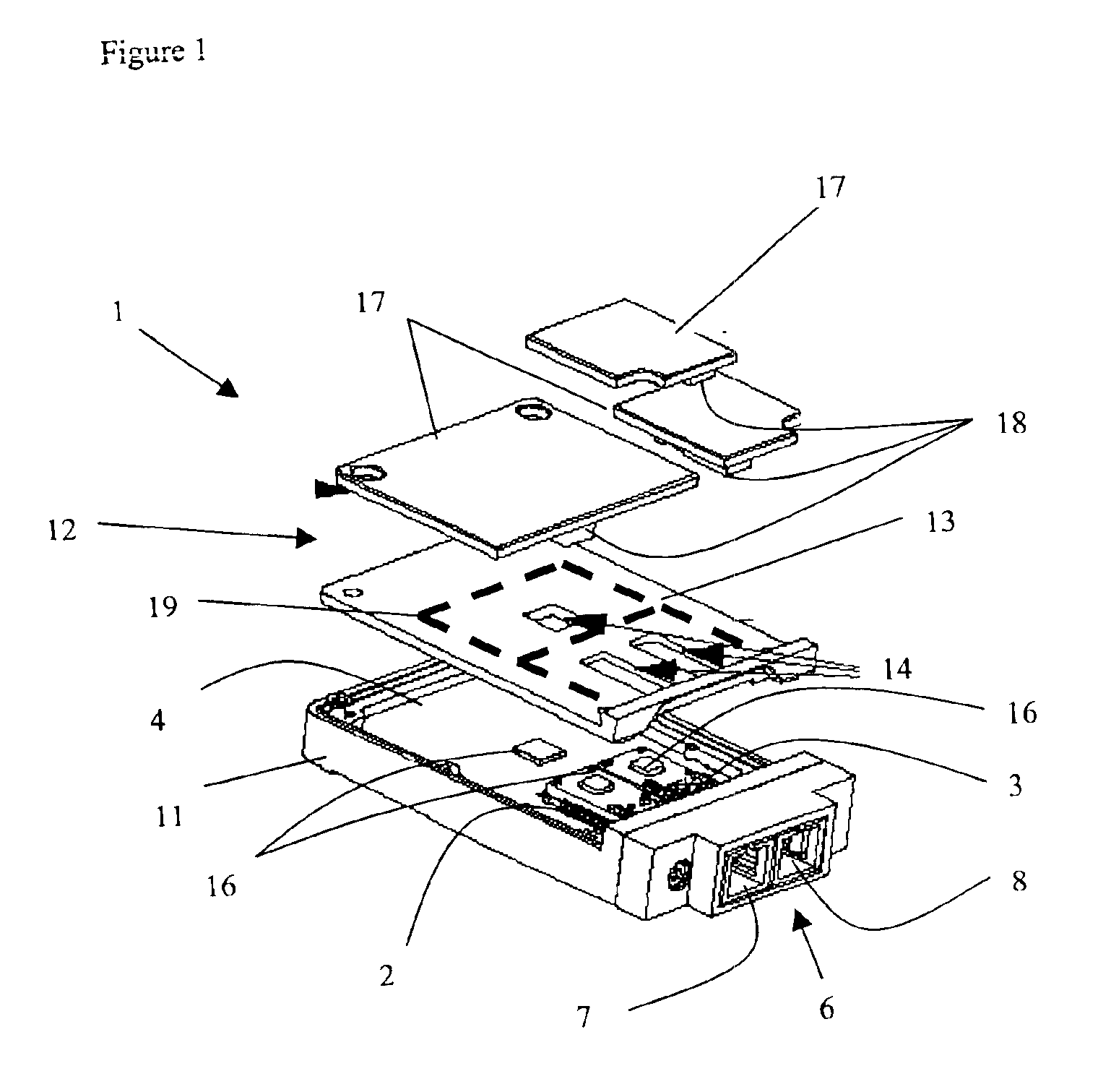
[0021]With reference to FIG. 1, an optical transceiver, generally indicated at 1, includes a transmitter optical sub-assembly (TOSA) 2 and a receiver optical sub-assembly (ROSA) 3, which are mounted on a printed circuit board 4. An optical connector 6 is disposed on one end of the optical transceiver 1, and includes an output port 7 for transmitting outgoing signals from the TOSA 2 and an input-port 8 for transmitting incoming signals to the ROSA 3. Ideally, the optical connector 6 is adapted to receive a conventional SC duplex optical connector, but any form of optical connector is within the scope of the invention. An electrical connector (not shown) is found on the other end of the optical transceiver 1 for electrically connecting the device to a printed circuit board in a host computer system. Typically, the electrical connector is in the form of electrical pins extending downwardly from the transceiver 1 through holes in the host computer's print circuit board for soldering the...


PUM


Abstract

The invention relates to modular heat-dissipating housing covers for opto-electronic modules, e.g. transceivers. The housing covers according to the present invention are constructed out of various different parts, which provide different levels of heat dissipation depending on the desired implementation, while maintaining a seal against EMI leakage. Extra heat sinking portions are provided to dissipate heat generated from specific heat generating sources. The extra heat sinking portions are configured into a shape and / or out of a material that provides more thermal dissipation than the standard cover provided. Independent control over the different heat sinking portions enables a better fit and appropriate dissipation.

Description

CROSS-REFERENCE TO RELATED APPLICATIONS[0001]The present invention claims priority from U.S. patent applications Ser. Nos. 60 / 361,654 filed Mar. 5, 2002 and 60 / 397,630 filed Jul. 23, 2002.TECHNICAL FIELD[0002]The present invention relates to a heat sink for an opto-electronic device, and in particular to a modular heat sink cover for an optical transceiver providing both thermal dissipation and electromagnetic interference shielding.BACKGROUND OF THE INVENTION[0003]Opto-electronic devices, e.g. optical transceivers, include optical subassemblies (OSA) for converting electronic signals into optical signals and / or vice versa. Optical transceivers include a transmitter optical subassembly (TOSA), which includes a laser, and a receiver optical subassembly (ROSA), which includes a photodiode detector. Conventional transceivers have not required specially designed heat sinks, as the metal housings or the electromagnetic interference (EMI) shielding have provided sufficient heat dissipatio...

Claims


Application Information

Patent Timeline
IPC IPC(8): G02B6/36G02B6/42H01L23/552H01R13/658H05K7/20
CPCG02B6/4201H05K7/20418H01L23/552H01R13/65802H01L2924/0002H01L2924/00G02B6/4256G02B6/4261G02B6/4269G02B6/4277H01R13/6582
Inventor BRANCH, SCOTT MICHAELDISTAD, EUGENE E.FREITAG, LADD W.HANLEY, MICHAEL FRANCISGAIO, DAVID PETER
Owner LUMENTUM OPERATIONS LLC
Features
  • Generate Ideas
  • Intellectual Property
  • Life Sciences
  • Materials
  • Tech Scout
  • Unparalleled Data Quality
  • Higher Quality Content
  • 60% Fewer Hallucinations
Learn More