
Remote sampling system

a sampling system and remote sampling technology, applied in the field of analytical systems, can solve the problems of inability to send real-time data, system limited operation time and depth range, and profilers with no permanent connection to the base station, so as to prolong the time of operation and increase the efficiency of analytical systems.

Inactive Publication Date: 2005-07-12
ECOLAB USA INC
View PDF5 Cites 18 Cited by
  • Summary
  • Abstract
  • Description
  • Claims
  • Application Information

AI Technical Summary

Benefits of technology

[0012]It is an object of the present invention to increase the efficiency of the analytical system; methods for automated sampling and measuring of various parameters at discrete depths and prolong the time of operation without human interference.
[0013]It is another object of the present invention to increase the depth range for the profiler and to improve the power efficiency of the overall operational methods.
[0014]It is a further object of the present invention to make the buoyancy of the profiler self-adjustable to outside pressure of different depths and provide a means to move the profiler from the water surface to maximum depth using low force drives.
[0018]The dynamic buoyancy compensator may be built as an active device when water is pumping in and out or as a passive device when the profiler has been moving to the target depth with an open input of the dynamic buoyancy compensator using an external force, for example, with the assistance of a motor-driven water propeller. For the passive device, water is forced in or out by the difference in pressure inside and outside of the passive dynamic buoyancy compensator. To improve accuracy, in some embodiment the dynamic buoyancy compensator may work in passive mode when approaching the target depth and in active mode when close to the target point.

Problems solved by technology

This profiler has no permanent connection with the base station and cannot send real time data.
This system has a limited operational time and depth range because air inside of said chamber is not separated from the water therefore during pumping cycles air will be gradually dissolved in the water, which is pumping in and out.
Such profiler uses electrical power with low efficiency and cannot work at a depth where water pressure is higher than the maximum pressure of the pump.
A guide line for guiding the profiler described in this patent provides additional friction during profiler movements that increases power consumption and adversely effects the accuracy of the system.

Method used


Image

  • Remote sampling system
  • Remote sampling system
  • Remote sampling system

Examples


Embodiment Construction

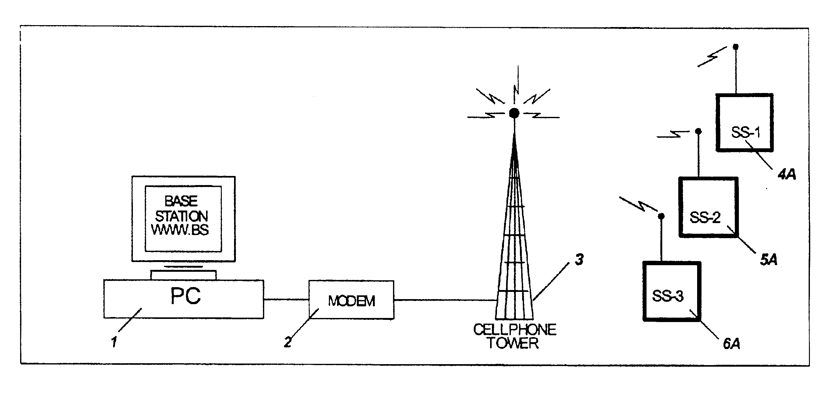
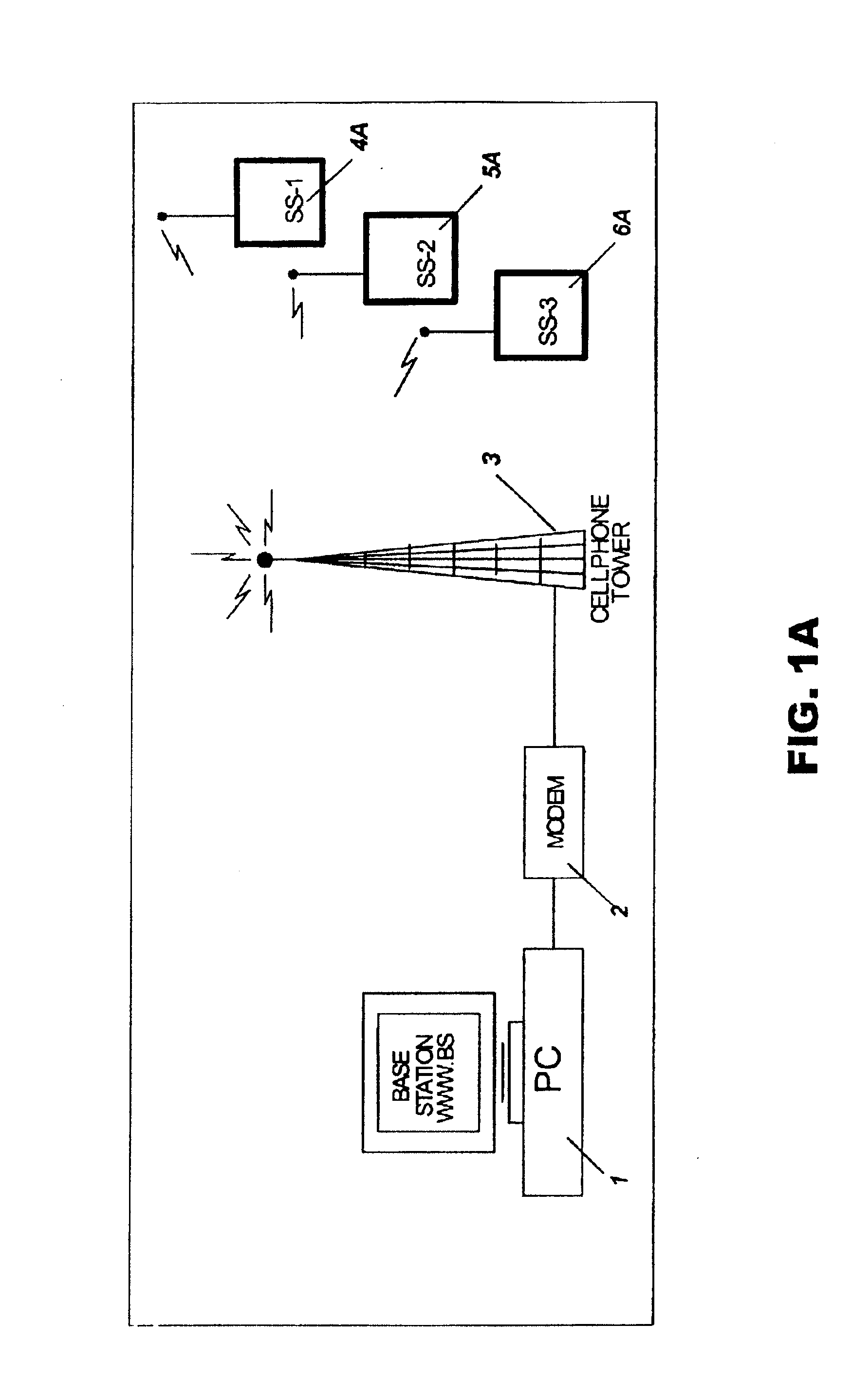
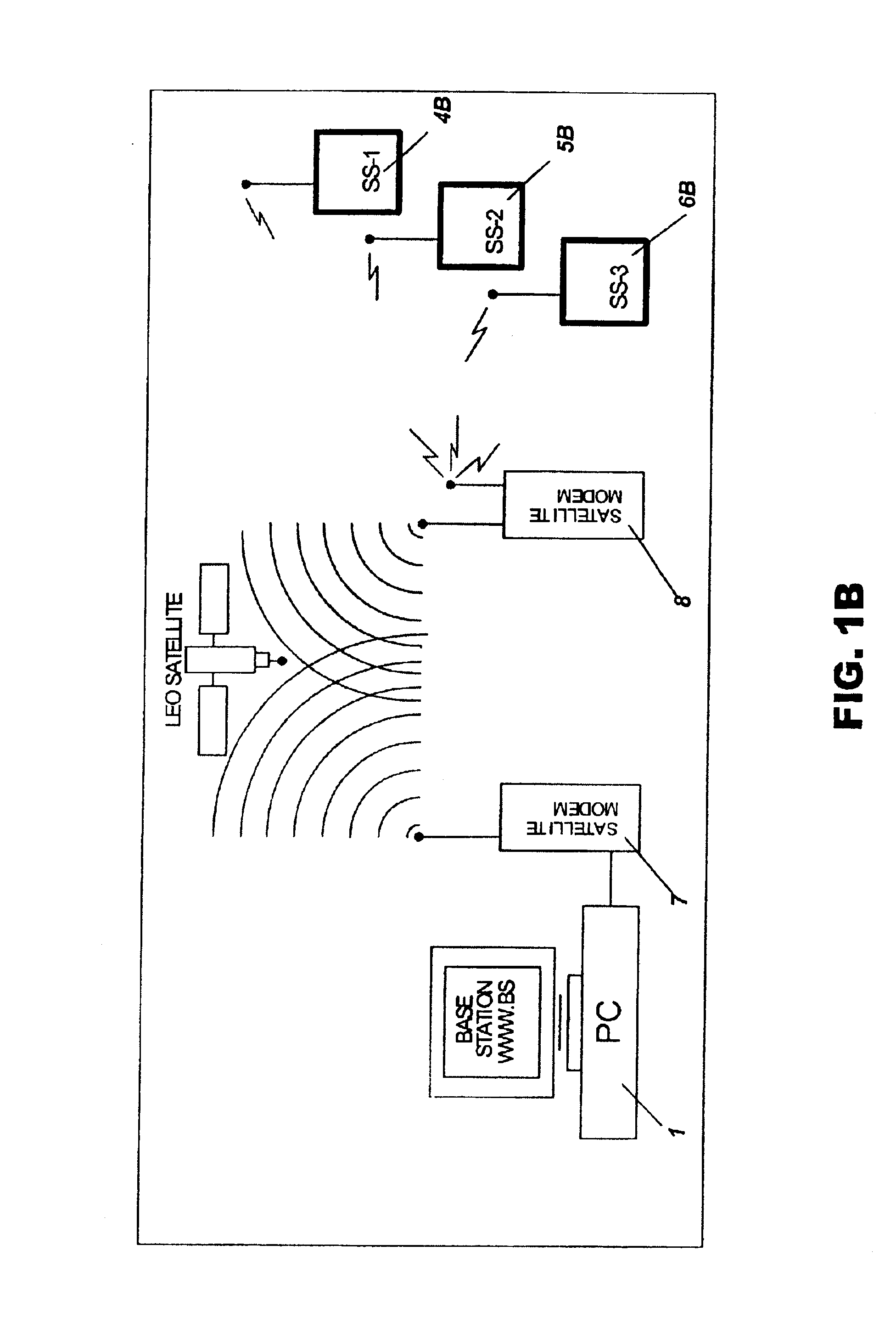
[0038]The remote sampling system, according to the present invention, includes a base station with computer or micro controller, a telecommunication device and one or several autonomous remote sampling stations. Three embodiments are shown in FIG. 1A, FIG. 1B and FIG. 1C.

[0039]The remote sampling station shown in FIG. 1A includes a base station with a personal computer 1 and a landline modem 2. The landline modem 2 through a cellular communication station 3 receives information from remote sampling stations 4A, 5A, 6A which are equipped with cellular modems.

[0040]The remote sampling station shown at the FIG. 1B includes a base station with a personal computer 1 and a satellite modem 7. The satellite modem 7 through the LEO (Low Earth Orbit) or other satellite system communicates with another satellite modem 8, which receives information from remote sampling stations 4B, 5B, and 6B. The satellite modem 8 and the remote sampling stations 4B, 5B and 6B are equipped with radio modems fo...


PUM

PropertyMeasurementUnit
depthaaaaaaaaaa
pressureaaaaaaaaaa
pressureaaaaaaaaaa

Abstract

An automated system for periodically sampling water bodies, such as lakes, and delivering the test results to a remote computer using a communication system. In particular, the system has a variable buoyancy profiler with a dynamic buoyancy compensator responding approximately linear to a water pressure created by an external water body so as to actively or passively interact with an external force or pressure thereby moving the profiler to a target depth.

Description

[0001]This application claims the benefit of U.S. Provisional Patent Applications Ser. No. 60 / 331,193 filed on Nov. 9, 2001, the entire disclosures of which are incorporated herein by reference.BACKGROUND OF THE INVENTION[0002]1. Field of the Invention[0003]The invention generally relates to analytical systems and methods for automated sampling and measuring of various parameters for environmental purposes, water management, process optimization and early warning system for monitoring, management and mitigation efforts. More particularly it relates to an automated system for the periodic profiling of water bodies like lakes, rivers, reservoirs and estuaries and delivering the test results to a remote computer using a communication system.[0004]2. Description of Related Arts[0005]The invention may be used for the remote measuring of environmental parameters using one or several autonomous stations having a deployment platform with a power supply system, controller unit and a communic...

Claims


Application Information

Patent Timeline
Patent Type & Authority Patents(United States)
IPC IPC(8): G01N1/14G01N33/18G01N35/00
CPCG01N1/14G01N35/00871C02F2209/02C02F2209/03G01N2001/021G01N2035/00881
Inventor TOKHTUEV, EUGENESKIRDA, ANATOLYSLOBODYAN, VIKTOROWEN, CHRISTOPHER
Owner ECOLAB USA INC
Learn More