Microvolume device employing fluid movement by centrifugal force

a centrifugal force and microfluidic technology, applied in the direction of crystal growth process, separation process, instruments, etc., can solve the problems of high labor intensity, time-consuming process of growing crystals with high diffraction quality, and high labor intensity of traditional methods for crystal growth and crystallization. to achieve the effect of convenient device rotation

Inactive Publication Date: 2005-07-12
TAKEDA SAN DIEGO
View PDF13 Cites 3 Cited by
  • Summary
  • Abstract
  • Description
  • Claims
  • Application Information

AI Technical Summary

Benefits of technology

[0058]In another embodiment, a microfluidic device is provided that comprises: a substrate; one or more microvolumes at least partially defined by the substrate, each microvolume comprising a first submicrovolume, a second submicrovolume where fluid in the first submicrovolume is transported to the second submicrovolume when the device is rotated about a first rotational axis, and a...

Problems solved by technology

Traditional methods for crystal growth and crystallization are highly labor intensive and require significant quantities of material to evaluate and optimize crystal growth conditions.
The process of growing crystals with high diffraction quality is time-consuming and involves trial-and-error experiment on multiple solution variables such as pH, temperature, ionic strength, and specific concentrations of salts, organic additives, and detergents.
In addition, the amount of highly purified protein is usually limited, multi-dimensional trials on these solution conditions are unrealistic, labor-intensive and costly.
Existing crystallization, such as hanging drop, sitting drop, dialysis and other vapor diffusion methods have the...

Method used


Image

  • Microvolume device employing fluid movement by centrifugal force
  • Microvolume device employing fluid movement by centrifugal force
  • Microvolume device employing fluid movement by centrifugal force

Examples


Embodiment Construction

[0161]The present invention relates to various methods, devices and kits relating to microfluidics.

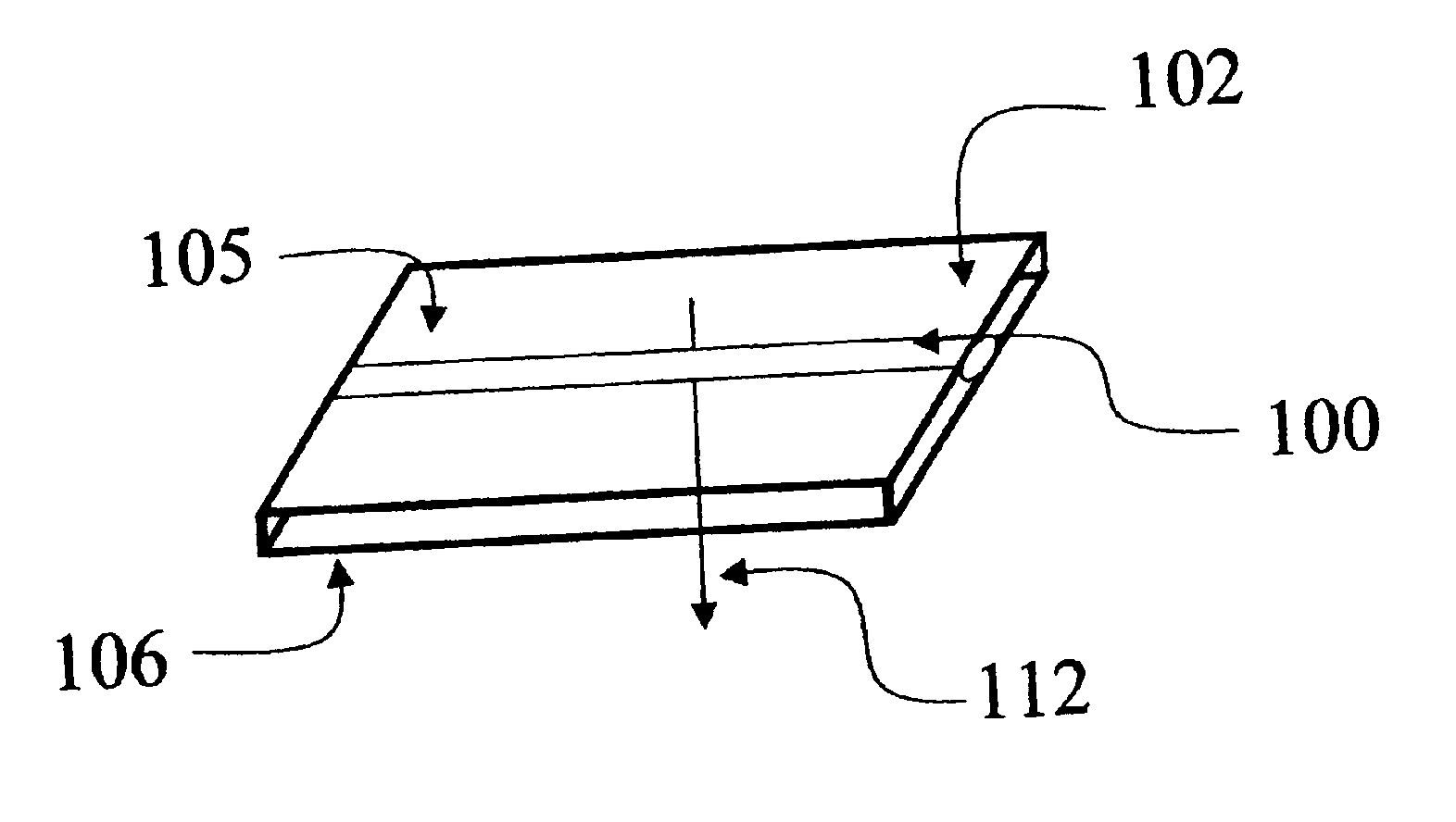
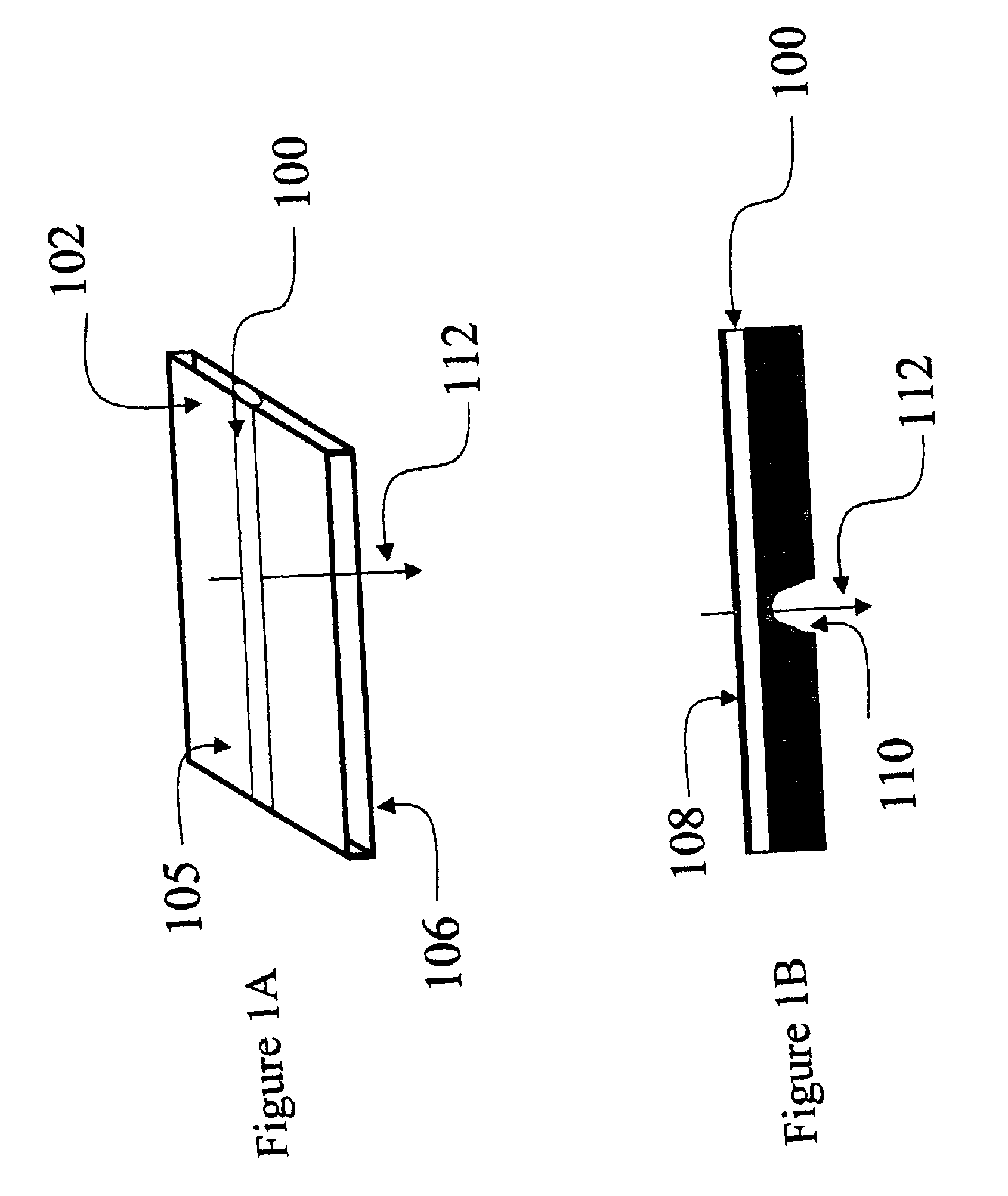
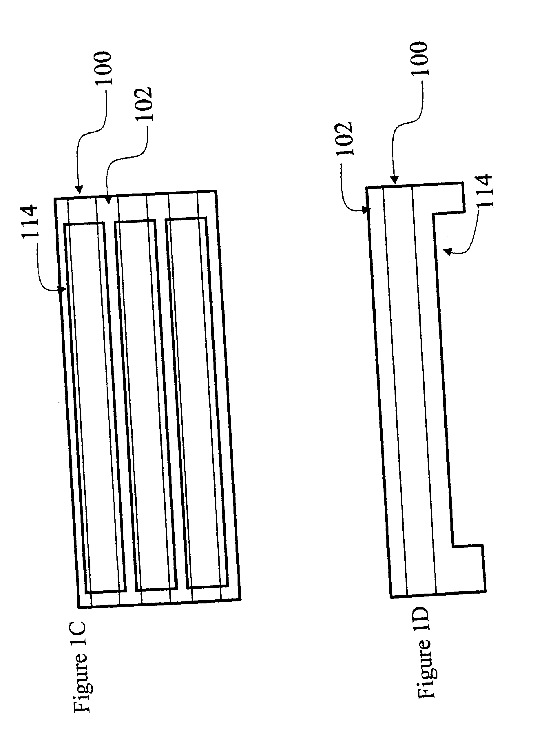
[0162]One particular aspect of the present invention relates to the use of these methods and devices for forming crystallization samples, transporting crystallization samples, and crystallizing materials therein, particularly on a microvolume scale, high throughput manner. Distinguishing the present invention in this regard is the performance of the crystallizations in very small, substantially enclosed volumes formed by or within a substrate, referred to herein as an “enclosed microvolume”. Other aspects of the present invention will be understood by one of ordinary skill in view of the teachings provided herein.

[0163]It is noted that many of the particular embodiments are described herein in regard to performing crystallization experiments. However, it should be understood that many of the operations involved in performing crystallization experiments (e.g., measuring, mixing, fluid f...


PUM

PropertyMeasurementUnit
Fractionaaaaaaaaaa
Fractionaaaaaaaaaa
Fractionaaaaaaaaaa

Abstract

A microfluidic device comprising: a substrate shaped so as to provide the device with an axis of rotation about which the device may be rotated; and a plurality of microvolumes at least partially defined by the substrate, each microvolume comprising a first submicrovolume and a second submicrovolume that is in fluid communication with the first submicrovolume when the device is rotated, the plurality of microvolumes being arranged in the device such that fluid in the first submicrovolumes of multiple of the microvolumes is transported to the second submicrovolumes of the associated microvolumes when the device is rotated about the rotational axis.

Description

RELATED APPLICATION[0001]This application is a continuation in part of U.S. patent application Ser. No. 09 / 877,405 filed Jun. 8, 2001, which is incorporated herein by reference.BACKGROUND OF THE INVENTION[0002]1. Field of the Invention[0003]The present invention relates to microfluidic devices and methods.[0004]2. Description of Related Art[0005]Traditional methods for crystal growth and crystallization are highly labor intensive and require significant quantities of material to evaluate and optimize crystal growth conditions. Examples of these methods include the free interface diffusion method (Salemme, F. R. (1972) Arch. Biochem. Biophys. 151:533-539), vapor diffusion in the hanging or sitting drop method (McPherson, A. (1982) Preparation and Analysis of Protein Crystals, John Wiley and Son, New York, pp 82-127), and liquid dialysis (Bailey, K. (1940) Nature 145:934-935).[0006]Presently, the hanging drop method is the most commonly used method for growing macromolecular crystals ...

Claims


Application Information

Patent Timeline
IPC IPC(8): C30B7/00G01N25/14G01N25/00
CPCC30B7/00G01N25/147C30B29/58B01J2219/00274Y10T117/1004B33Y80/00
Inventor DAVID, PETER R.
Owner TAKEDA SAN DIEGO
Why Eureka
Try Eureka