Low power plasma generator

a plasma generator, low-power technology, applied in the direction of plasma technique, coating, electric discharge lamps, etc., can solve the problems of reducing power efficiency, limiting the amount of power and vacuum levels that can be used, and the source being inoperable in a short period of time, so as to achieve convenient fabrication, reduce the effect of power consumption and low cos

Active Publication Date: 2005-07-12
NORTHEASTERN UNIV
View PDF8 Cites 29 Cited by
  • Summary
  • Abstract
  • Description
  • Claims
  • Application Information

AI Technical Summary

Problems solved by technology

Portable operation of microplasma sources places a limit on the amount of power and the vacuum levels that can be employed as well as on the maximum temperature the discharge can reach.
In view of the small dimensions of a miniaturized plasma source, even damage on the order of microns can become catastrophic and render the source inoperable in a short period of time.
This source operates well but has a relatively low Q of the order of about 40, which results in lower power efficiency.
In addition, the structure is susceptible to failure as ions are accelerated by a plasma sheath voltage that forms between the plasma and the microstrip line.
Ion erosion inherent in the design limits the usable lifetime of the device and wastes power, as power is expended in the ion erosion process rather than in the intended plasma generation.

Method used


Image

  • Low power plasma generator
  • Low power plasma generator
  • Low power plasma generator

Examples


Embodiment Construction

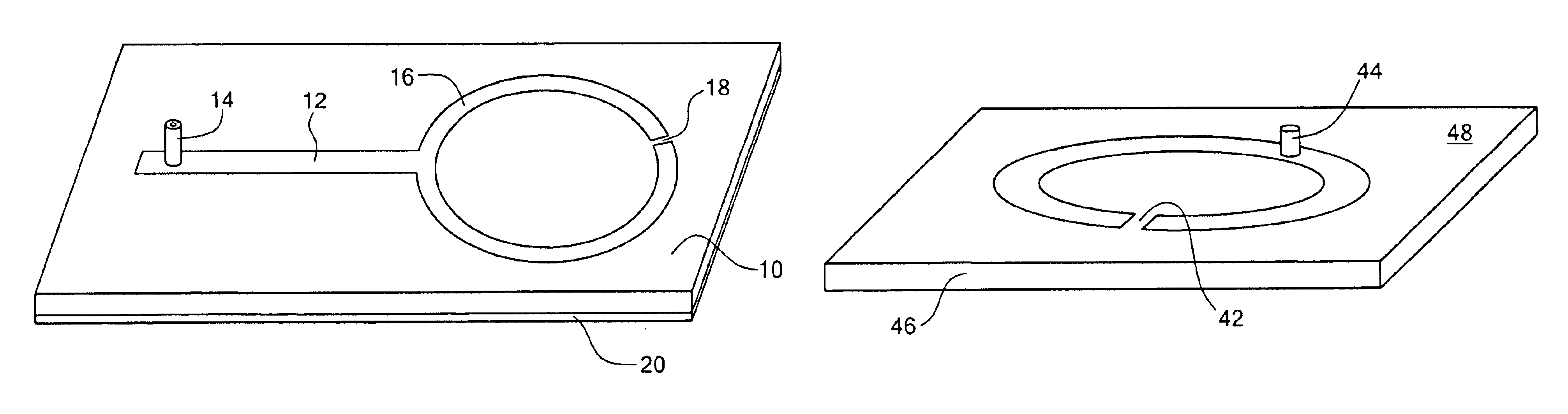
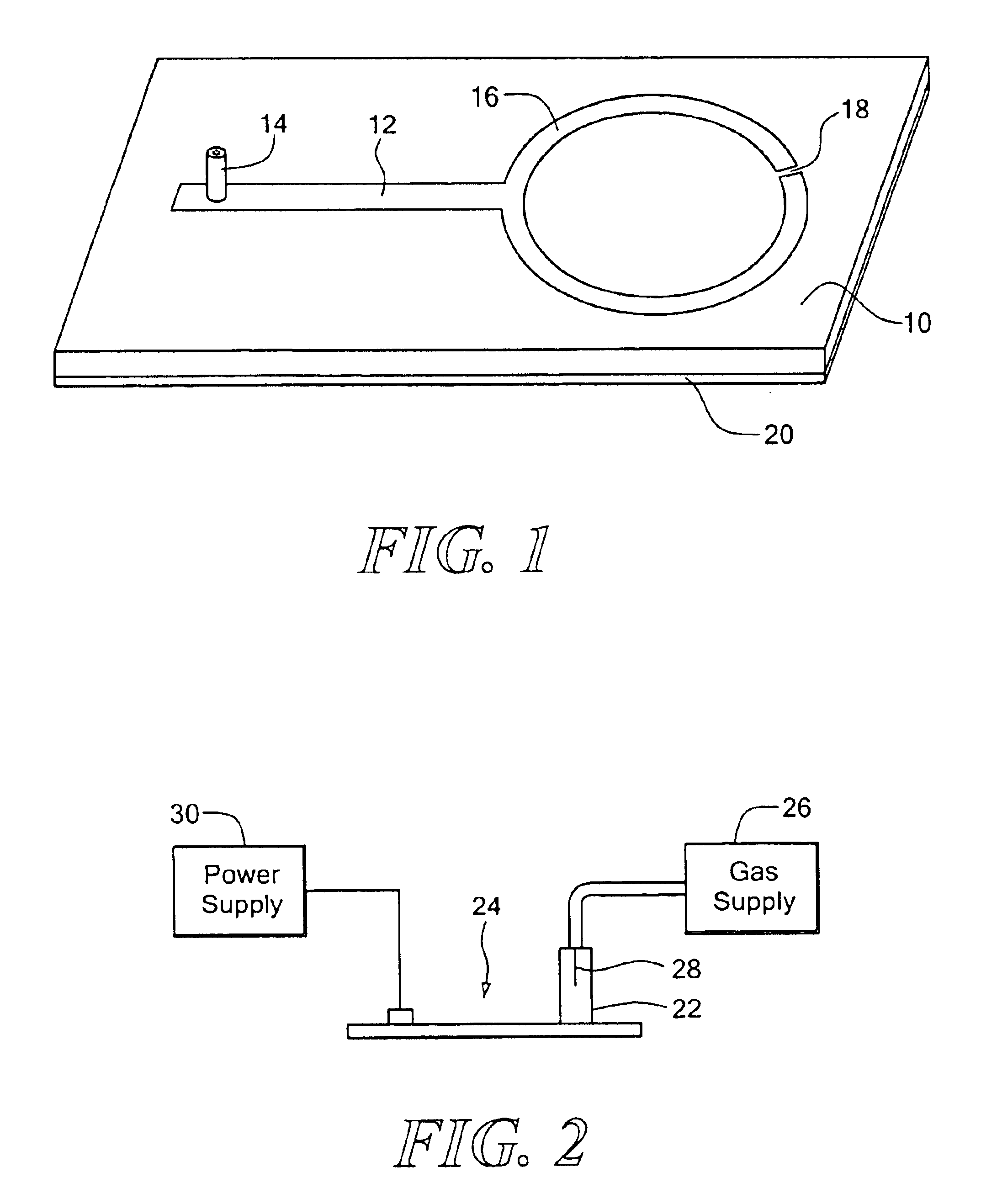
[0021]An embodiment of the invention is illustrated in FIG. 1. A substrate 10 of dielectric material has provided thereon a stripline 12 connected at one end to a coaxial connector 14 and at the other end to a high Q split ring resonator 16 having a gap 18 in the plane of the substrate. The stripline is one-quarter wavelength (λ / 4) in length at the operating frequency and serves as a quarter wave transformer to match the ring resonator impedance to the impedance of a power supply which energizes the generator. The impedance is typically 50 ohms. The circumference of the ring resonator is one-half wavelength (λ / 2) at the operating frequency. The angle between the discharge gap and the centerline of the ring is such that the impedance measured at the power input at connector 14 is matched to that of the power supply. A ground plane 20 is provided on the opposite side of the substrate 10 from the resonant ring. The voltages at the resonator ends at the gap 18 are 180° out of phase, and...


PUM

PropertyMeasurementUnit
lengthaaaaaaaaaa
lengthaaaaaaaaaa
lengthaaaaaaaaaa

Abstract

A low power plasma generator is provided which can be fabricated in micro-miniature size and which is capable of efficient portable operation. The plasma generator comprises a microwave stripline high Q resonant ring, which may be circular or non-circular, disposed on a dielectric substrate and having a discharge gap in the plane of the substrate. The resonant ring is one-half wavelength in circumference at the operating frequency and is matched to the impedance of the microwave power supply. The voltages at the resonator ends at the gap are 180° out of phase and create an intense electric field in the gap, and a resultant discharge across the gap. The discharge is non-thermal and operates near room temperature and has an intense optical emission. The generator is well suited for low power portable and other applications and can be readily fabricated by known microcircuit techniques. Alternatively, the gap of the resonant ring can extend through the substrate and in which the discharge is formed. A bias coil can be coupled to the ring to provide a bias voltage to the plasma. A feedback path can be provided for self oscillation and closed loop frequency control.

Description

CROSS REFERENCE TO RELATED APPLICATIONS[0001]Applicant claims the benefit under 35 U.S.C. § 119(e) of prior U.S. provisional application Ser. No. 60 / 436,982 filed Dec. 30, 2002, the disclosure of which is incorporated herein by reference.STATEMENT REGARDING FEDERALLY SPONSORED RESEARCH OR DEVELOPMENT[0002]This invention was made with government support. The U.S. Government has certain rights in this invention.BACKGROUND OF THE INVENTION[0003]There is a need for miniaturized plasma sources that can be integrated in portable or other devices for many applications such as bio-sterilization, small scale materials processing and microchemical analysis systems. Portable operation of microplasma sources places a limit on the amount of power and the vacuum levels that can be employed as well as on the maximum temperature the discharge can reach. For portable applications it is desirable to operate the discharge source at atmospheric pressure in order to eliminate the need for vacuum pumps. ...

Claims


Application Information

Patent Timeline
Patent Type & Authority Patents(United States)
IPC IPC(8): H05H1/24H05H1/46
CPCH05H1/24H05H1/46H05H1/4622
Inventor HOPWOOD, JEFFREY A.IZA, FELIPE
Owner NORTHEASTERN UNIV
Why Eureka
Try Eureka