

Fire heat sensor
a heat sensor and fire technology, applied in fire alarms, calorimeters, instruments, etc., can solve the problems of inability to easily distinguish the level of a temperature difference complex differential heat sensing circuits, and inability to easily discriminate from the level of a temperature difference, so as to reduce the dependence on the direction of hot airflow and eliminate signal processing
- Summary
- Abstract
- Description
- Claims
- Application Information
AI Technical Summary
Benefits of technology
Problems solved by technology
Method used
Image

Examples
first embodiment
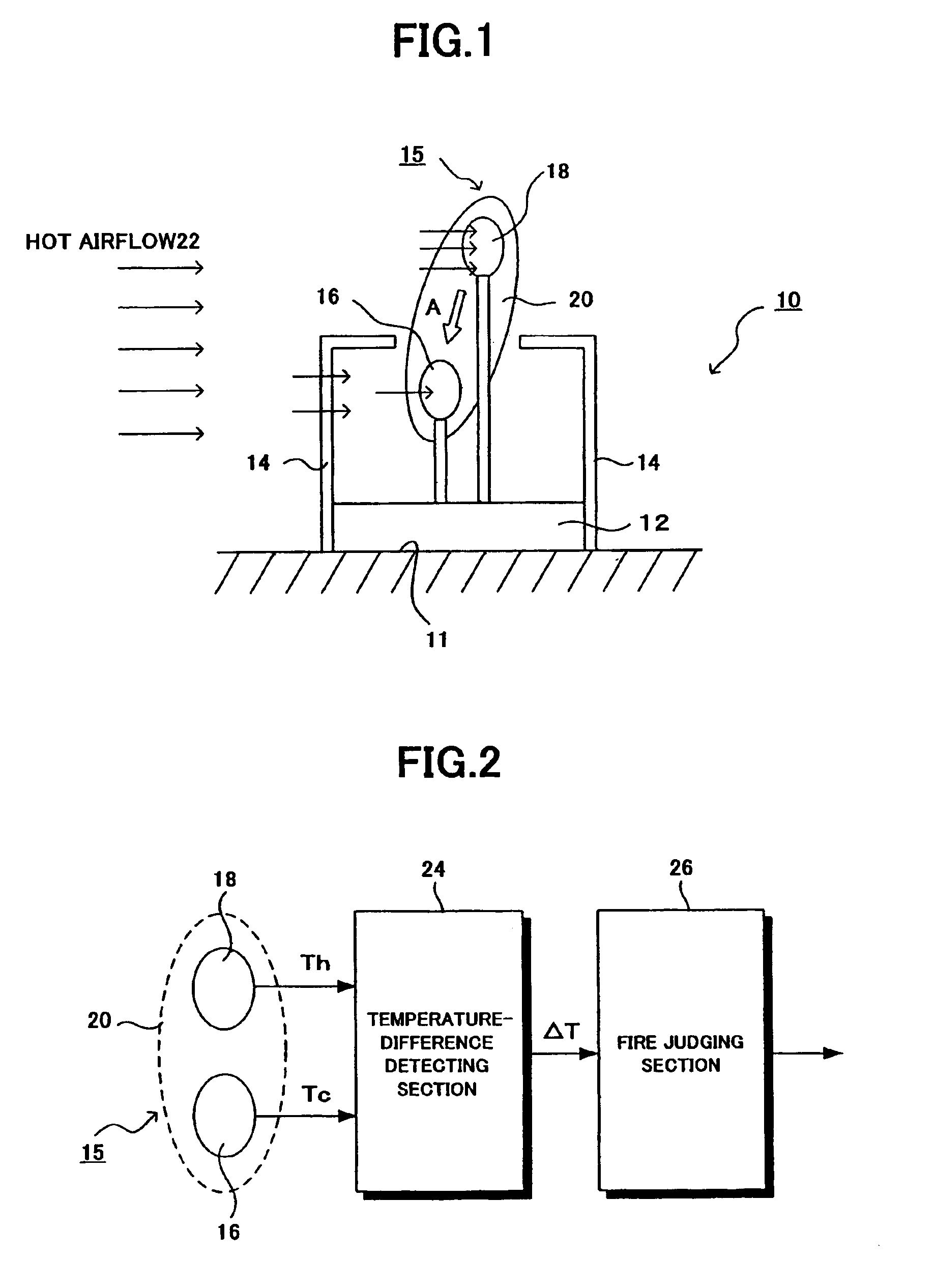
[0048]Referring to FIG. 1, there is depicted a fire heat sensor 10 constructed in accordance with the present invention. In the figure, the fire heat sensor 10 includes a main body 12, and a guard member 14 formed on the main body 12. The main body 12 is installed on a mounting surface 11 such as a ceiling. The guard member 14 has an opening in which a sensor portion 14 is situated.
[0049]The sensor portion 15 has a temperature detecting element 16 which constitutes a low-temperature detecting portion, and a temperature detecting element 18 which constitutes a high-temperature detecting portion. The temperature detecting element 16 and the temperature detecting element 18 are formed integrally with each other by a resin member 20 consisting of synthetic resin such as epoxy resin, etc.
[0050]The temperature detecting element 16 which constitutes the low-temperature detecting portion of the sensor portion 15 is situated within the guard member 14 and at a position that is not exposed di...
seventh embodiment
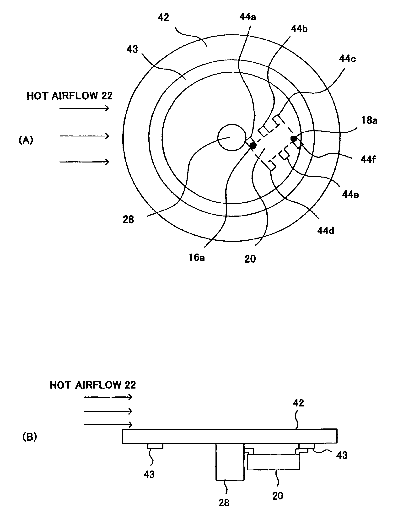
[0094]FIG. 10 shows a sensor portion constructed in accordance with the present invention. As shown in FIG. 10A in the sensor portion 15, a transistor 16a for low-temperature detection and a transistor 18a for high-temperature detection are provided as the temperature detecting elements. The sensor portion 15 has 6 (six) lead terminals 44a to 44f, which correspond to the collectors, emitters, and bases of the two transistors 16a and 18a. These components are formed as a package device by a resin member 20 molded.
[0095]The collector of the transistor 16a of the low-temperature detection portion is connected directly to the lead terminal 44a. The emitter lead 46a of the transistor 16a is connected to the lead terminal 44b. The base lead 46b of the transistor 16a is connected to the lead terminal 44d.
[0096]The collector of the transistor 18a of the high-temperature detection portion is connected directly to the lead terminal 44f. The emitter lead 46c of the transistor 18a is connected...
eighth embodiment
[0098]FIG. 11 shows a sensor portion constructed in accordance with the present invention. In the package device structure of this embodiment, as shown in FIG. 11A, a diode 16b for low-temperature detection, a diode 18b for high-temperature detection, and a resin member 20 are formed as a package device structure by resin molding. When molding the resin member 20, four lead terminals 48a to 48d are integrally molded.
[0099]The cathode of the diode 16b of the low-temperature detecting portion of the sensor portion 15 is connected directly to the lead terminal 48a, while the anode is connected to the lead terminal 48b through a lead 50a. The cathode of the diode 18b of the high-temperature detecting portion of the sensor portion 15 is connected directly to the lead terminal 48d, while the anode is connected to the lead terminal 48c through a lead 50b.
[0100]The sensor portion 15 with a package device structure housing the two transistors 16b and 18b is mounted on a printed board 42 sho...
PUM
 Abstract
Description
Claims
Application Information