
Apparatus and method for cooling integrated circuit devices

a technology of integrated circuit devices and cooling devices, which is applied in the direction of domestic cooling devices, insulated conductors, cables, etc., can solve the problems of insufficient heat dissipation, substantial heating, and conventional techniques such as using solid metal heat sinks on top of processors, and passing air through extended surfaces of heat sinks

Active Publication Date: 2005-07-12
INTEL CORP
View PDF5 Cites 60 Cited by
  • Summary
  • Abstract
  • Description
  • Claims
  • Application Information

AI Technical Summary

Benefits of technology

The patent text describes a method and apparatus for cooling integrated circuit devices, particularly in the context of one rack unit (1U) server computers. The invention is about addressing the challenge of cooling high-performance processors that are commonly used in these servers, as traditional cooling methods such as heat sinks and air cooling are not sufficient to keep up with the increasing clock rates of modern processors. The invention proposes a new cooling system that uses a thermosiphon, which is a cooling system that uses a remote heat exchanger and thermoelectric elements to cool the processor. The system is designed to be efficient in cooling the processor while keeping it within the 1U server chassis. The technical effect of the invention is to provide a more effective and efficient way of cooling high-performance processors in server computers.

Problems solved by technology

Unfortunately, as the ISP's customer base grows, the ISP's data center is required to house additional servers in order to provide Internet access to new customers.
However, although 1U servers may be compact in size, such servers are required to provide continuously increasing data throughput levels.
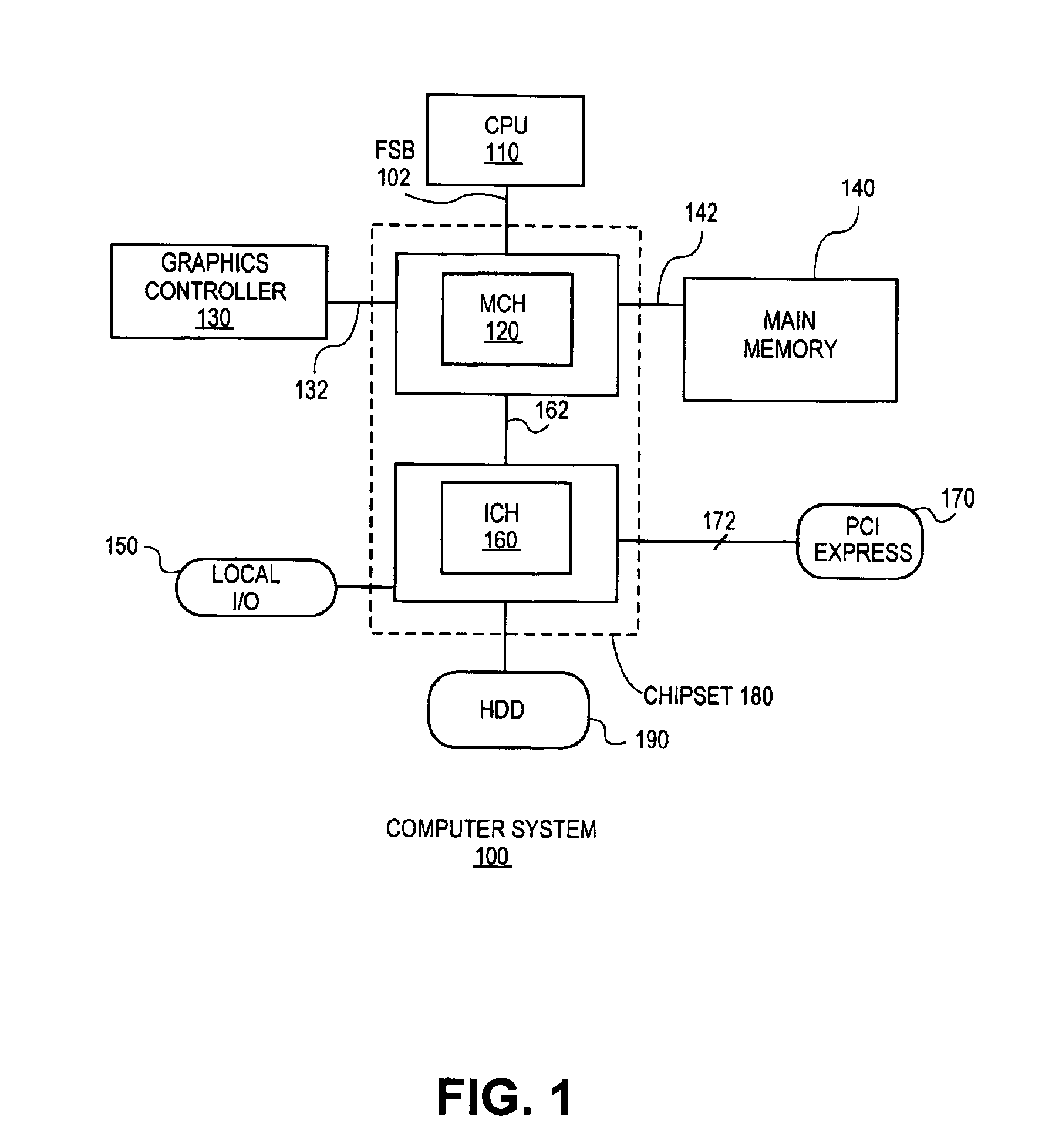
However, the increased clock rates and processing speeds of corresponding IU processors result in substantial heating when incorporated within a 1U server.
Consequently, conventional techniques, such as using a solid metal heat sink on top of the processor, while passing air through extended surfaces of the heat sink, are insufficient for dissipating heat produced by modern days 1U processors.

Method used


Image

  • Apparatus and method for cooling integrated circuit devices
  • Apparatus and method for cooling integrated circuit devices
  • Apparatus and method for cooling integrated circuit devices

Examples


Embodiment Construction

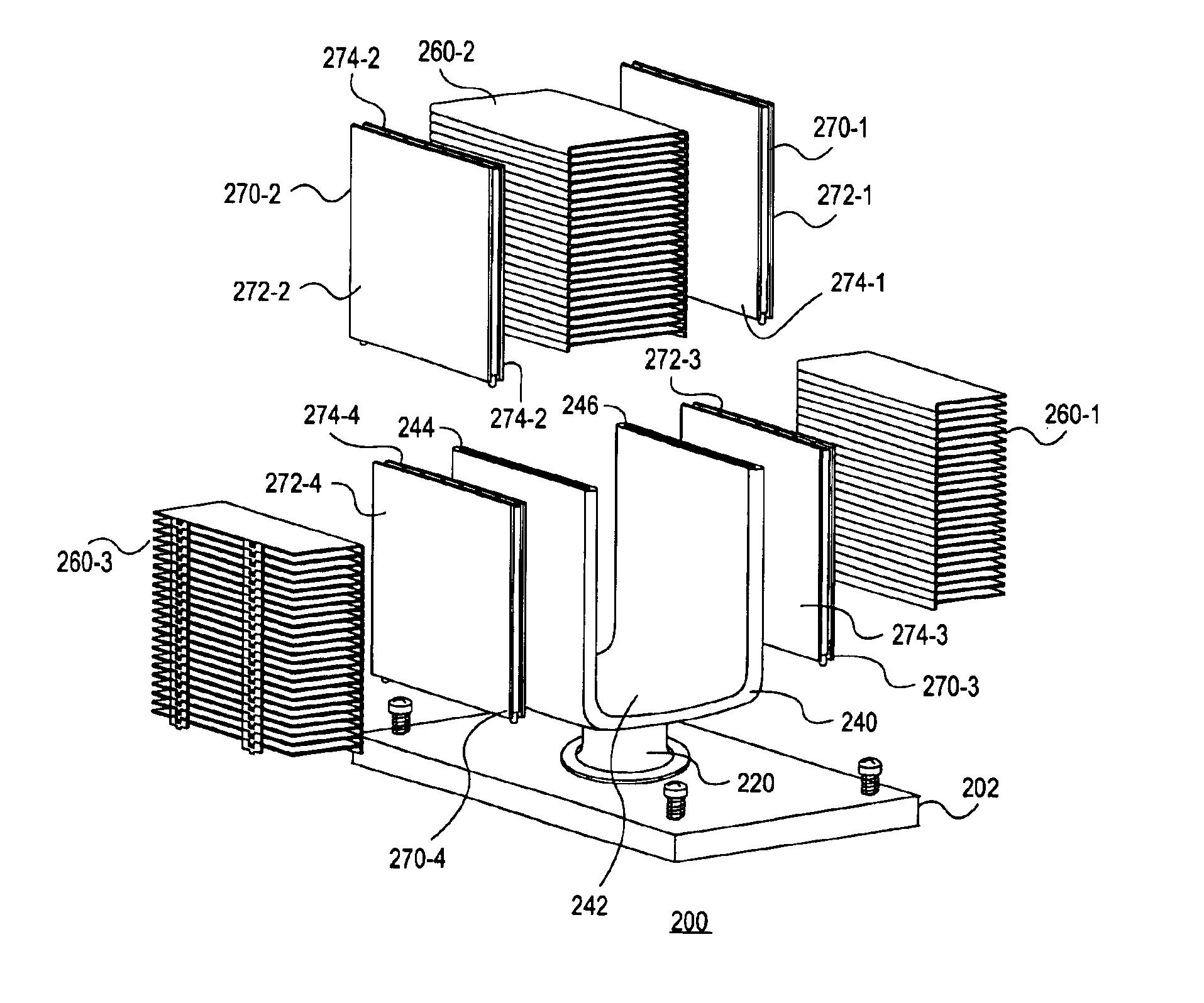
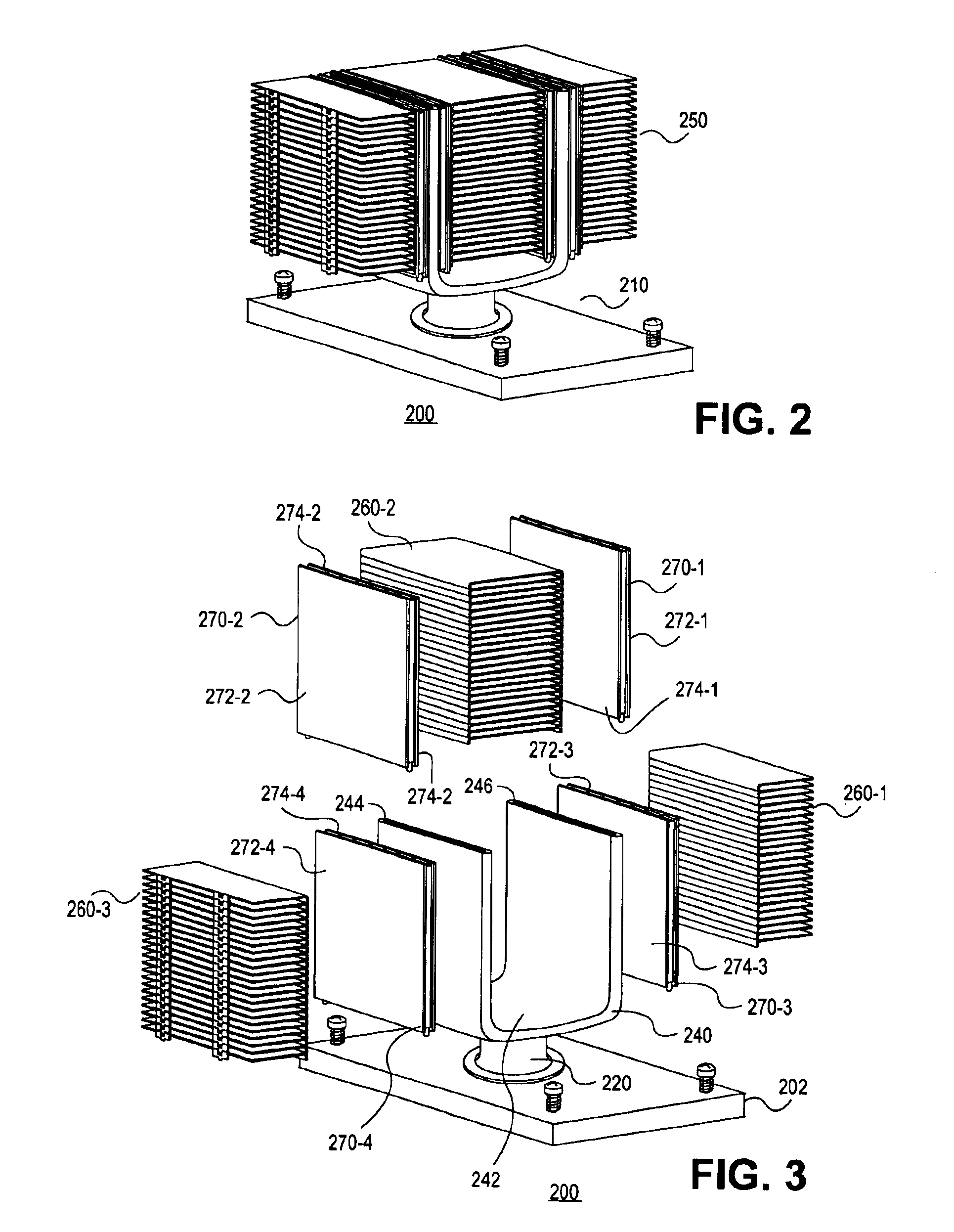
[0015]A method and apparatus for cooling integrated circuit devices are described. In one embodiment, the apparatus includes a thermosiphon having an evaporator portion coupled to a first surface of a heat source. A condenser portion of the thermosiphon is coupled to the evaporator portion distal from the first surface of the heat source. At least one thermoelectric element is coupled to the condenser portion of the thermosiphon. A remote heat exchanger is coupled to the at least one thermoelectric element.

[0016]In one embodiment, the remote heat exchanger, the thermoelectric elements and the condenser portion of the thermosiphon are located outside a chassis of a one rack unit (1U) server computer. Accordingly, by placing the remote heat exchanger, the thermoelectric element and the condenser portion of the thermosiphon outside the 1U server chassis, heat absorbed by the device is cooled by ambient air. In one embodiment, the condenser portion of the thermosiphon is cooled by power...


PUM


Abstract

Some embodiments of a method and apparatus for cooling integrated circuit devices are described. In one embodiment, the apparatus includes a thermosiphon having an evaporator portion coupled to a first surface of a heat source and a condenser portion coupled to the evaporator portion distal from the first surface of the heat source. A remote heat exchanger is coupled to the condenser of the thermosiphon. In addition, one or more thermoelectric elements are coupled between the heat exchanger and the condenser of the thermosiphon. In one embodiment, the remote heat exchanger, the thermoelectric elements and the condenser portion of the thermosiphon are located outside a chassis of a one rack unit (1U) server computer.

Description

FIELD OF THE INVENTION[0001]One or more embodiments of the invention relate generally to the field of integrated circuit and computer system design. More particularly, one or more of the embodiments of the invention relates to a method and apparatus for cooling integrated circuit devices.BACKGROUND OF THE INVENTION[0002]The advent of the Internet provides Internet users with a worldwide web of information at the click of a button. As the Internet continues to grow and occupy a ubiquitous position within society, Internet service providers are continuously in competition for providing users with Internet access. Generally, Internet service providers (ISPs) use one or more server computers, which are designed to provide customers of the ISP with Internet access. Unfortunately, as the ISP's customer base grows, the ISP's data center is required to house additional servers in order to provide Internet access to new customers.[0003]Accordingly, central processing unit (CPU) space is at a...

Claims


Application Information

Patent Timeline
Patent Type & Authority Patents(United States)
IPC IPC(8): H05K7/20H01L23/427
CPCH01L23/427H01L2924/0002H01L2924/00
Inventor ERTURK, HAKANSAUCIUC, IOANUNREIN, EDGAR J.
Owner INTEL CORP
Learn More