Fastening assembly and method for fastening a multi-layered laminate together

a multi-layered laminate and fastening technology, applied in the direction of threaded fasteners, sheet joining, shrinkage connections, etc., can solve the problems of reducing the strength of the structure, reducing the weight savings of overdesigned joints, and increasing the overall weight, so as to reduce the stress concentration through the thickness of the laminate and facilitate installation

Inactive Publication Date: 2005-07-19
NOVATOR
View PDF14 Cites 43 Cited by
  • Summary
  • Abstract
  • Description
  • Claims
  • Application Information

AI Technical Summary

Benefits of technology

[0013]An advantage of the present invention is that a well defined interference fit is provided between the fastener device and the throughhole in the laminate.
[0014]Another advantage is that the stress concentration through the thickness of the laminate is minimized.
[0015]Yet another advantage is that the weight of the fastener assembly is less than that of known fasteners.
[0016]A further advantage is that the fastener can be easily installed in the throughhole of the laminate using an automated assembly process.

Problems solved by technology

In bolted composite structures, stress concentrations develop around the holes, severely reducing the strength of the structure.
The regions containing holes must, therefore, be reinforced, resulting in an overall weight increase.
Overdesigned joints can easily reduce the weight savings which are possible through the use of composite materials.
In particular, factors such as type of fastener, fastener / hole tolerance and lateral constraint affect the strength and fatigue life.
In critical joints in thick composite structures, the non-uniform contact stress distribution through the thickness reduces the static strength and fatigue life of the structure significantly.
The countersink reduces the static strength and fatigue life of bolted joints as compared with joints that have protruding head fasteners.
Previously, it has been difficult in a production environment to machine a hole in an aircraft structure such that the hole has a complex geometry, i.e., such that an inner surface of the hole is curved or parabolic along its length.
Because of this machining difficulty, complex fastener and hole geometries have not been previously used.
As the joint is loaded, bolt 16 bends and tilts in hole 18 causing a stress concentration through the thickness, which may significantly reduce the strength of the laminate.
A special problem when using interference fit fasteners in laminated composite materials is the risk for damaging the laminate when installing the fastener in the hole.
A severe disadvantage of existing aerospace fastener systems is the need for nuts or collars at the exit side of the hole or anchorage of the fastener. FIG. 3 shows a Hucktite type of lock bolt installed in a composite laminate.
The parts of the fastener used for anchorage (shank and collar) represent a significant amount of the weight of the fastener.
Moreover, the need for collars makes installation of blind rivets difficult in composite materials since the collar may cause damage to the composite material in the installation process.
This is a well-known problem in the aircraft industry.

Method used


Image

  • Fastening assembly and method for fastening a multi-layered laminate together
  • Fastening assembly and method for fastening a multi-layered laminate together
  • Fastening assembly and method for fastening a multi-layered laminate together

Examples


Embodiment Construction

[0025]It is now possible, using automated high speed machining techniques, to cost effectively machine high precision straight diameter and conical countersinks. Such techniques allow the machining of complex fastener hole geometries without increasing tool cost or machining time. Hence, it is now possible to implement such machine tools in production environments. Such techniques can be used for machining holes in critical structures, thereby providing significant advantages with regard to strength, fatigue life, weight savings, and productivity.

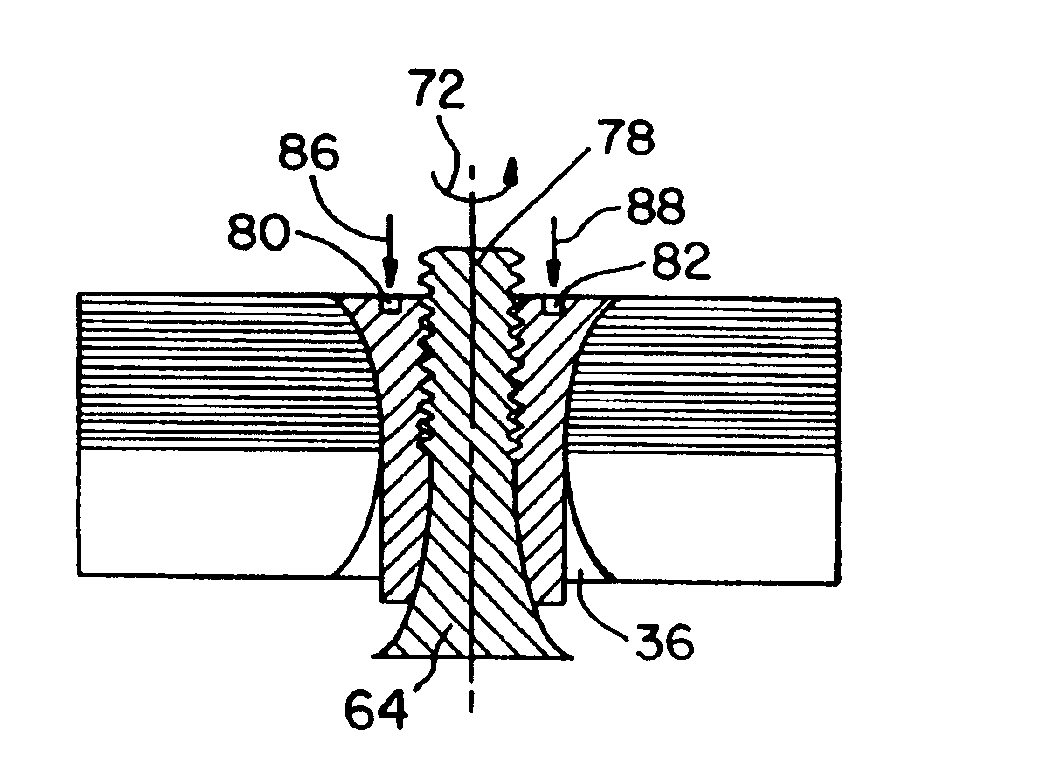
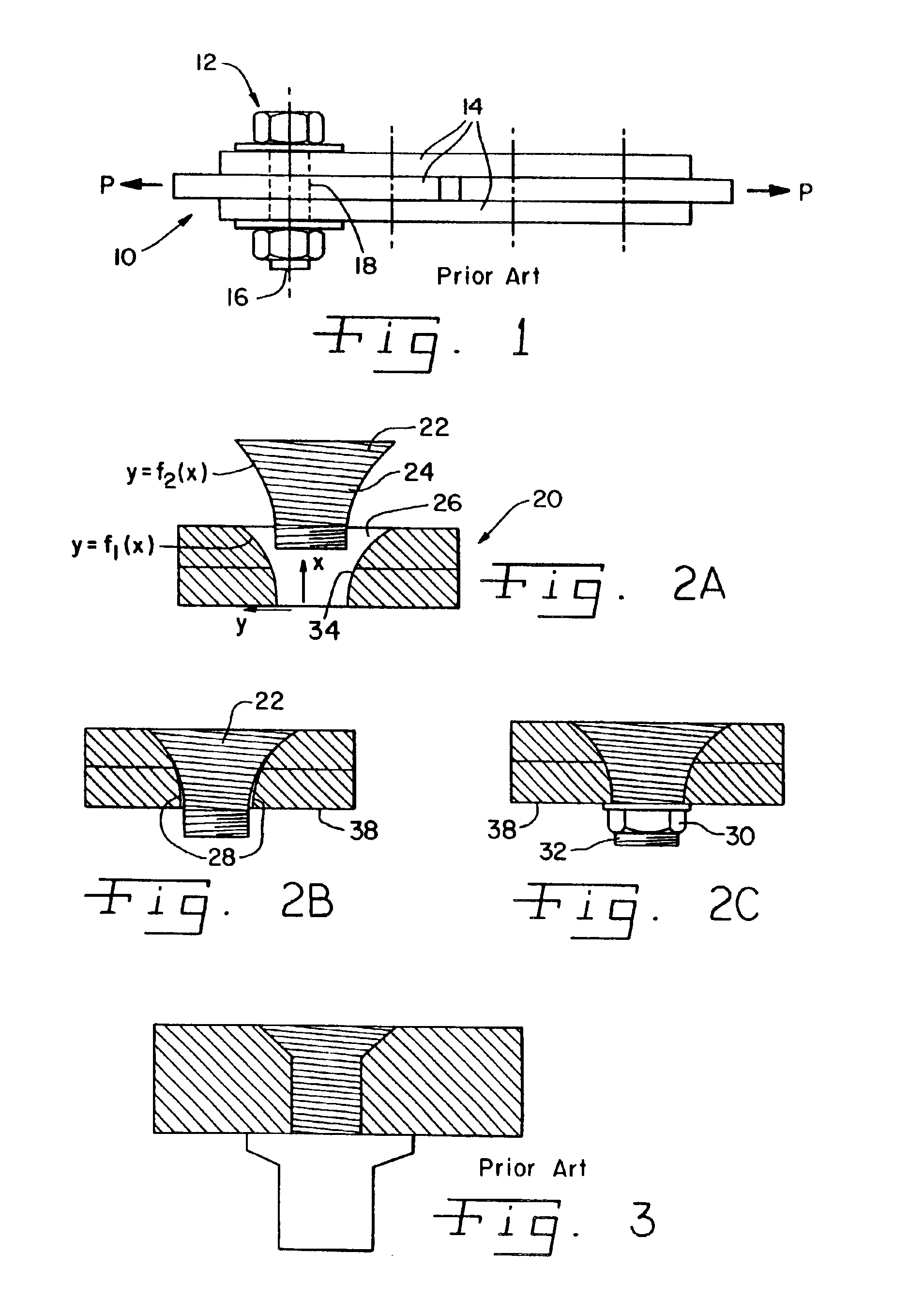
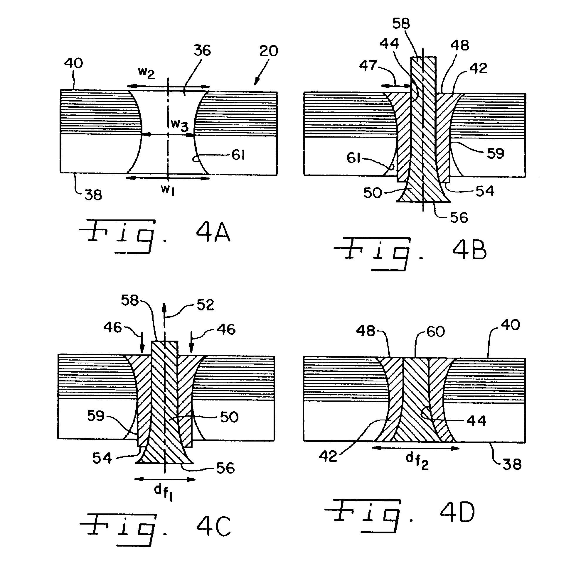
[0026]A multi-layered laminate such as a composite laminate 20 (FIG. 2a) is fastened by a fastener 22 with a complex shaped shank 24. The shank geometry is defined by the function y=f2(x). Fastener 22 is installed into a hole 26 with a complex shaped hole edge geometry defined by the function y=f1(x), wherein the second derivative of y is positive for any value of x. That is, the diameter of hole 26 increases at an increasing rate in direct...


PUM

PropertyMeasurementUnit
stress concentrationaaaaaaaaaa
lengthaaaaaaaaaa

Abstract

A fastener assembly is inserted into a throughhole of a composite laminate to thereby fasten the composite laminate together. The throughhole has a length extending from a first outer surface of the composite laminate to a second outer surface of the composite laminate. The throughhole has a first width at the first outer surface, a second width at the second outer surface, and a third width at a point along the length of the throughhole between the first outer surface and the second outer surface. The third width is less than each of the first width and the second width. The fastener assembly includes a substantially annular fastener device having an axial opening and a peripheral surface substantially conforming to the inner surface of the throughhole. An elongate element is tightly received within the axial opening of the fastener device and biases the peripheral surface of the fastener device against the inner surface of the throughhole such that both the fastener device and the elongate element are substantially entirely disposed between the first outer surface and the second outer surface of the composite laminate.

Description

CROSS REFERENCE TO RELATED APPLICATIONS[0001]The application is continuation of Ser. No. 09 / 458,871 filed on Dec. 10, 1999 now U.S. Pat. No. 6,405,425, based upon U.S. provisional patent application Ser. No. 60 / 111,967, entitled “FASTENING CONCEPTS FOR INCREASED STRENGTH AND FATIGUE LIFE IN AIRCRAFT STRUCTURES”, filed Dec. 11, 1998, and U.S. provisional patent application Ser. No. 60 / 125,921, entitled “FASTENING CONCEPTS FOR INCREASED STRENGTH AND FATIGUE LIFE IN AIRCRAFT STRUCTURES, filed Mar. 23, 1999, the complete disclosures of which are hereby expressly incorporated by reference.BACKGROUND OF THE INVENTION[0002]1. Field of the Invention[0003]The present invention relates to fastening devices, and, more particularly, to fastening devices for fastening a composite laminate together.[0004]2. Description of the Related Art[0005]Mechanical properties of graphite composites make them attractive for structural applications, such as in aircraft and spacecraft, where high strength and s...

Claims


Application Information

Patent Timeline
Patent Type & Authority Patents(United States)
IPC IPC(8): F16B5/02F16B4/00
CPCF16B4/004F16B5/02Y10T29/49956Y10T29/49948
Inventor ERIKSSON, INGVAR
Owner NOVATOR
Why Eureka
Try Eureka