Reverse battery protection for a trolling motor

a technology for trolling motors and batteries, which is applied in the direction of safety/protection circuits, emergency protection arrangements for automatic disconnection, field or armature current control, etc. it can solve the problems of unanticipated activation, easy to reverse the connection of such clips with respect to the polarity of the battery, and catastrophic failure of the electronic circuitry controlling the motor and steering system. , to achieve the effect of low loss, high impedance and low impedan

Inactive Publication Date: 2005-07-19
BRUNSWICK CORPORATION
View PDF19 Cites 26 Cited by
  • Summary
  • Abstract
  • Description
  • Claims
  • Application Information

AI Technical Summary

Benefits of technology

[0011]The present invention provides a trolling motor having reverse battery protection which is relatively inexpensive and which results in relatively low losses. The reverse battery protection comprises a power metal oxide field effect transistor (“MOSFET”), connected in series with the primary power supplied to the trolling motor. In a preferred embodiment, MOSFET having an intrinsic diode is connected such that the intrinsic diode is forward biased when the battery is properly connected and reverse biased when the battery is reversed. The gate terminal is connected to the opposite rail of the power supply than that switched by the transistor. Thus, the MOSFET is driven to its on, or conductive, state when the battery is properly connected but is switched to its off state, or non-conductive, state when the battery is connected backwards. Since the device is switched off and the intrinsic diode is reverse biased when the battery is reverse connected, virtually no current will flow. In its conductive state, the MOSFET will typically exhibit very low impedance, on the order of a few milliohms, while in its non-conductive state, the MOSFET will exhibit very high impedance, in fact virtually infinite impedance.

Problems solved by technology

Unfortunately, it is easy to inadvertently reverse the connection of such clips with respect to the polarity of the battery.
Unprotected, reverse battery connection can cause problems ranging from unanticipated activation of the trolling motor to catastrophic failure of the electronic circuitry controlling the motor and steering system.
Unfortunately, in the diode protection scheme, all of the trolling motor current must passes through the diode.
In addition, in light of the large currents flowing through the diode, as well as the voltage drop across the diode, significant amounts of heat are produced which must be dissipated in the environment and which reduce the efficiency of the trolling motor.
While this eliminates virtually all of the heat loss of the diode scheme, the relay is somewhat large and costly, and energy is spent energizing the coil.

Method used


Image

  • Reverse battery protection for a trolling motor
  • Reverse battery protection for a trolling motor
  • Reverse battery protection for a trolling motor

Examples


Embodiment Construction

[0024]Before explaining the present invention in detail, it is important to understand that the invention is not limited in its application to the details of the construction illustrated and the steps described herein. The invention is capable of other embodiments and of being practiced or carried out in a variety of ways. It is to be understood that the phraseology and terminology employed herein is for the purpose of description and not of limitation.

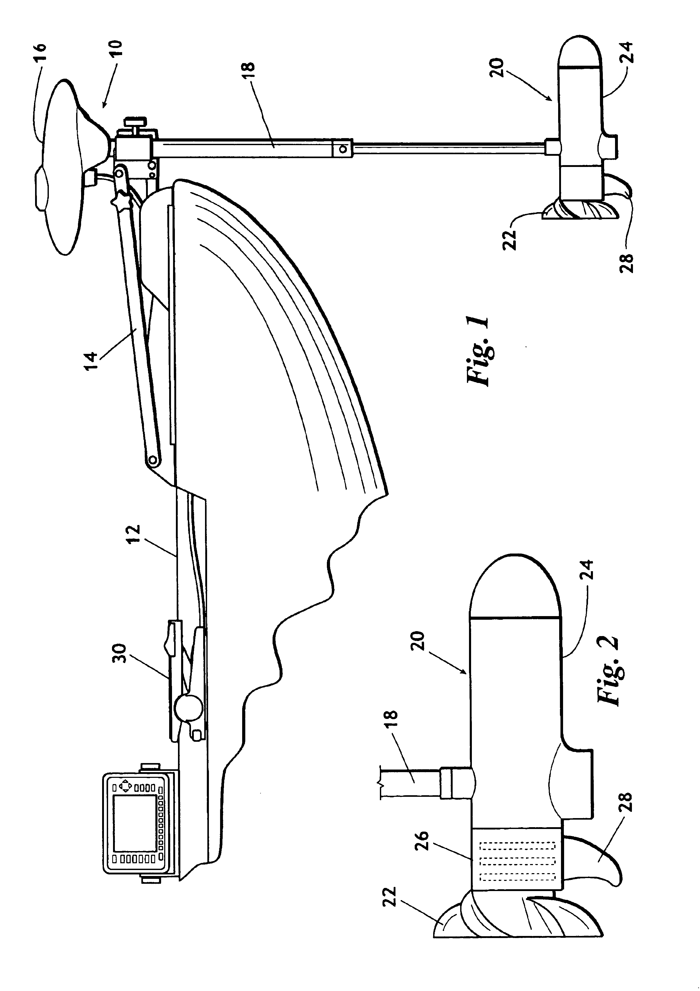
[0025]Referring now to the drawings, wherein like reference numerals indicate the same parts throughout the several views, a trolling motor 10 having reverse battery protection is shown in its general environment in FIG. 1. Typically trolling motor 10 is rotatably mounted to a fishing boat 12 by a mount 14. Mount 14 allows the trolling motor to be placed in the water, as shown in FIG. 1, or to be laid on the deck of boat 12 when not in use. Preferably, trolling motor 10 includes: head 16 which typically houses a steering mechanism and...


PUM


Abstract

A trolling motor having reverse battery protection such that an inadvertent reversal of the battery leads, as when connecting the trolling motor to a battery, will not cause unwanted operation of the trolling motor or damage to the trolling motor circuitry. The reverse battery protection includes a field effect transistor connected in series between one of the battery leads and the motor. The gate terminal of the transistor is in communication with the other battery lead such that, when the battery leads are properly connected to a battery, the transistor is driven to its conducting state and, when the battery leads are reversed, the transistor is driven to its non-conducting state.

Description

BACKGROUND OF THE INVENTION[0001]1. Field of the Invention[0002]The present invention relates to electrical trolling motors for a fishing boat More particularly, but not by way of limitation, the present invention relates to system to protect the electronic circuitry of a trolling motor from unintentional reverse battery connection.[0003]2. Background of the Invention[0004]Trolling motors are well known in the art and, most often, employ a permanent magnet DC motor. Generally speaking, a trolling motor is a relatively small electric motor coupled to a propeller for propelling a boat, or other water craft, at a relatively low speed. Typically, the electric motor and propeller are positioned at the bottom of a support column rotatably supported by a bracket which is attached to the boat. Traditionally, a control head located at the top of the support column houses electronic circuitry for controlling the motor. In addition, the control head may also house a steering motor and associat...

Claims


Application Information

Patent Timeline
Patent Type & Authority Patents(United States)
IPC IPC(8): G05B11/28G05B11/01B63H20/00H02H11/00H02J7/00H02P7/00H02P7/29
CPCH02J7/0034H02P7/0044H02P7/29B63H20/007H02H11/003H02P7/04
Inventor HEALEY, ROBERT W.
Owner BRUNSWICK CORPORATION
Why Eureka
Try Eureka