Delta-sigma modulator system and method

a modulator and delta-sigma technology, applied in the field ofsignal processing, can solve the problems of preventing the recovery of information, causing noise in the sampled signal, and affecting the operation of the circuit, so as to improve the noise suppression and noise shaping effect, increase the size, complexity, or power requirements of the circui

Inactive Publication Date: 2005-07-19
CSR TECH INC
View PDF22 Cites 47 Cited by
  • Summary
  • Abstract
  • Description
  • Claims
  • Application Information

AI Technical Summary

Benefits of technology

[0031]In consideration of the problems inherent in the current state of the art, it would be advantageous to have a multiple-order sigma-delta modulator which achieves improved noise suppression and noise shaping without unnecessarily increasing the size, complexity, or power requirements of the circuit.

Problems solved by technology

In a general example using a 1-bit ADC, there will be a considerable amount of quantization error as a continuous analog signal is converted into a 1-bit digital signal limited by the fixed reference signal.
The addition of those aliased frequency components typically creates noise in the sampled signal and will generally prevent recovery of the information contained between 40 and 50 kHz in the original signal.
The quantization error resulting from the analog-to-digital conversion is typically known as quantization noise.
Because of the complexity of this quantization noise, it is usually very difficult to accurately represent mathematically.
However, because general higher-order modulators usually require high-order feedback loops, instability has typically been seen in some high-order delta-sigma modulators.
In fact, this assumption is almost never true.
Therefore, in such instances, the white noise assumption may not lead to extensive unexpected spurious signals in the output.
However, delta-sigma modulation of DC, periodic, or some manner of steady-state signals, many of which are regularly found in audio, speech, or frequency synthesizing applications, will generally not produce the good noise shaping and suppression predicted using the white noise assumption.
As the input signal and noise begin forming correlations, it becomes increasingly difficult to separate the signal from the noise as the signal is processed.
As a result, the correlations produce discrete spurious components in the output and reduce the modulator's overall effective noise suppression and dynamic range.
Because the increased spurious signal content arises due to the correlations formed between the input signal and the quantization noise, dithering typically counteracts the correlation by essentially adding noise to the system at some point.
Therefore, to implement dithering, the circuit size, complexity, and power requirement of the delta-sigma modulator must increase.
Therefore, as the resolution becomes smaller, there will typically be more spurious signals over a given frequency range.
This increase in spurious signal components generally begins to appear or act like white noise, thus effectively decorrelating the input signal from the quantization noise.
This small change actually results in a very large increase in circuitry to accommodate the larger word length.
Thus, implementing the increased word length also requires an increased circuit size and complexity.
Therefore, as with each of the preceding methods, using a higher-ordered delta-sigma modulator typically requires an increased circuit size and complexity.
One of the practical consequences of designing higher order delta-sigma modulators is that the quantization noise shaped to higher frequencies may reach very large signal powers because of the high order high pass noise shaping applied to the quantization noise.
However, in practice, circuit design problems arise due to the large signal power that peaks at fs / 2.
One such problem is that the fs clock signal can couple into sensitive bias circuits that power the signal path components thereby causing high-powered, out-of-band tones to demodulate down to baseband and severely degrade the SNR and spurious free dynamic range of the delta-sigma modulator.
Another commonly found problem in practical circuits is that components in a system using a delta-sigma modulator may cause the same above-described effect due to the second order intermodulation performance of these components.
The problem with each of the preceding noise reduction techniques arises from the necessity to use additional components and circuitry.

Method used


Image

  • Delta-sigma modulator system and method
  • Delta-sigma modulator system and method
  • Delta-sigma modulator system and method

Examples


Embodiment Construction

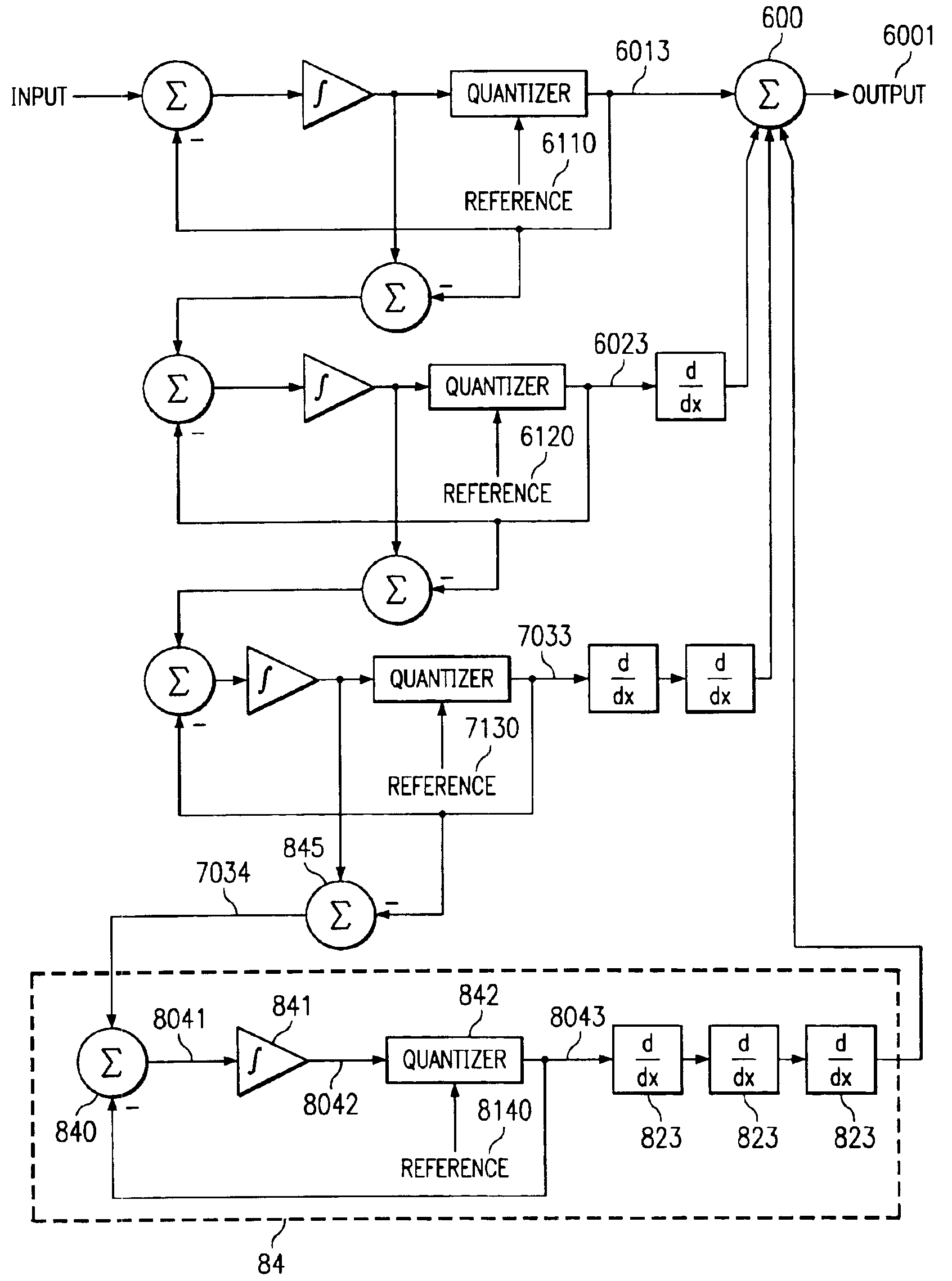
[0052]A preferred embodiment of the present invention enhances the noise characteristics of multi-order delta-sigma modulators by preferably including a quantizer in every modulator stage after the first, which may be selectively programmed to vary the reference signal associated therewith. To achieve the improved response, the preferred embodiment of the present invention would vary the subsequent stages' reference signals to be different from the first stage reference signal.

[0053]FIG. 6 shows a preferred embodiment of the present invention configured as a digital MASH second-order delta-sigma modulator. The inventive system generally receives input signal 6000 into stage one modulator 61. Input signal 6000 typically passes through stage one summer 610 which subtracts stage one output signal 6013 to form stage one intermediate signal 6011. Stage one intermediate signal 6011 is then usually integrated by integrator 611 to form stage one integrated signal 6012, which is then typical...


PUM


Abstract

The invention discloses a system and method for improving the out-of-band noise response of a multi-order delta-sigma modulator. The system and method includes programmable delta-sigma modulators which may be programmed to vary the reference signals at each modulator stage subsequent to the first stage relative to the reference signal of the first modulator stage. The resulting signal output will then typically exhibit the enhanced noise suppression characteristics of a dithered signal without the added circuitry and power required of a dithering apparatus.

Description

TECHNICAL FIELD[0001]This invention generally relates to signal processing and in particular to the use of delta-sigma modulation.BACKGROUND[0002]Delta-sigma modulation is used widely throughout signal processing applications. Any application that requires signal modulation may generally take advantage of delta-sigma modulation techniques. The basic digital-to-analog and analog-to-digital conversion capabilities of a delta-sigma modulator along with its superior linearity and noise-shaping attributes find extensive functionality in digital and analog signal processing for audio or speech applications as well as telecommunication and signal acquisition technologies. Delta-sigma modulation can be found in audio conversion applications for communication transmission, ISDN applications, modems, audio play-back equipment such as compact disc (CD) or digital versatile / video disc (DVD) players, signal or frequency synthesizers, or any other application or equipment which utilizes modulatio...

Claims


Application Information

Patent Timeline
Patent Type & Authority Patents(United States)
IPC IPC(8): H03L7/197H03M3/02H03L7/16
CPCH03L7/1976H03M7/3008H03M7/3022H03M3/50
Inventor BOLTON, JR., JERRY THOMAS
Owner CSR TECH INC
Why Eureka
Try Eureka