Method and system for detecting, timing, and correcting impulse noise

a technology of impulse noise and correction method, applied in the field of receiving apparatus for data communication system, can solve the problems of affecting the quality and rate of data transmission, affecting the integrity and reliability of such data transmission, and ignoring the compensation of impulse/burst noise, so as to solve the vulnerability of impulse noise, detect and cancel the generated noise, and the effect of less complex and expensiv

Inactive Publication Date: 2005-07-19
RPX CORP
View PDF4 Cites 80 Cited by
  • Summary
  • Abstract
  • Description
  • Claims
  • Application Information

AI Technical Summary

Benefits of technology

[0022]The new technique for detecting and canceling strong impulses can be used in conjunction with multitone transmission schemes, such as DMT and VCMT, to solve their vulnerability to impulse noise. However, the new method is not limited to multitone modulations, but also is suitable for other types of communication schemes, such as CDMA and single carrier modulation, and even non-communication signals. Furthermore, by applying the present method but switching the model time and frequency axes, the invention can be used to acquire the frequency of fast rising or changing ingresses (narrow band interference) and cancel them accordingly. In addition, in some data transmission and reception schemes, received and amplified signals may be subjected to clipping. The effect of clipping on a signal is similar to that produced by impulse noise. The present invention may also be adapted to detect and cancel noise generated by clipping, thus permitting the use of less complex and expensive receiving circuits.

Problems solved by technology

The integrity and reliability of such data transmissions can be compromised by several factors, such as transmission imperfections, receiving imperfections, and physical channel interference.
Examples of interference which affect the quality and rate of data transmission include impulses (or bursts), and other short duration events, and long duration interference, such as ingresses.
However, compensating for impulse / burst noise has received little attention.
Impulse or burst noise can be caused by many uncontrollable events, such as arcing and electrical transients coupled through a power system, lightning, etc.
Because it is broad band in effect, impulse noise is of particular concern in multi-carrier transmission schemes since the impulse noise may affect many, or even all channels simultaneously.
If a sub-channel is particularly noisy, it may not be used at all.
However, there is a tradeoff when resistance to impulse noise is considered.
However, strong impulses are very damaging to DMT transmission because the impulse may simultaneously corrupt all of the 256 symbols occupying the 256 DMT sub-channels.
Similarly, strong impulses are also very damaging to VCMT transmissions because the impulse can corrupt the symbols occupying every VCMT sub-channel at the time the impulse hits.
In addition, because VCMT uses spectral shaping, neighboring symbols may also be corrupted by the impulse.
However, it is considerably more complex to implement.
However, the techniques disclosed in the '264 patent are incapable of handling impulses having more than one degree of freedom (e.g., spanned by a basis of more than one vector).
However, the '440 patent does not adequately address in-band impulse noise.
However, none of these prior art impulse detection and compensation schemes provides a robust and efficient impulse detection system which can adequately detect impulses which have two or more unknown (or varying) degrees of freedom.
Further, none discloses an efficient scheme for handling strong impulses in a multi-channel transmission system.

Method used


Image

  • Method and system for detecting, timing, and correcting impulse noise
  • Method and system for detecting, timing, and correcting impulse noise
  • Method and system for detecting, timing, and correcting impulse noise

Examples


Embodiment Construction

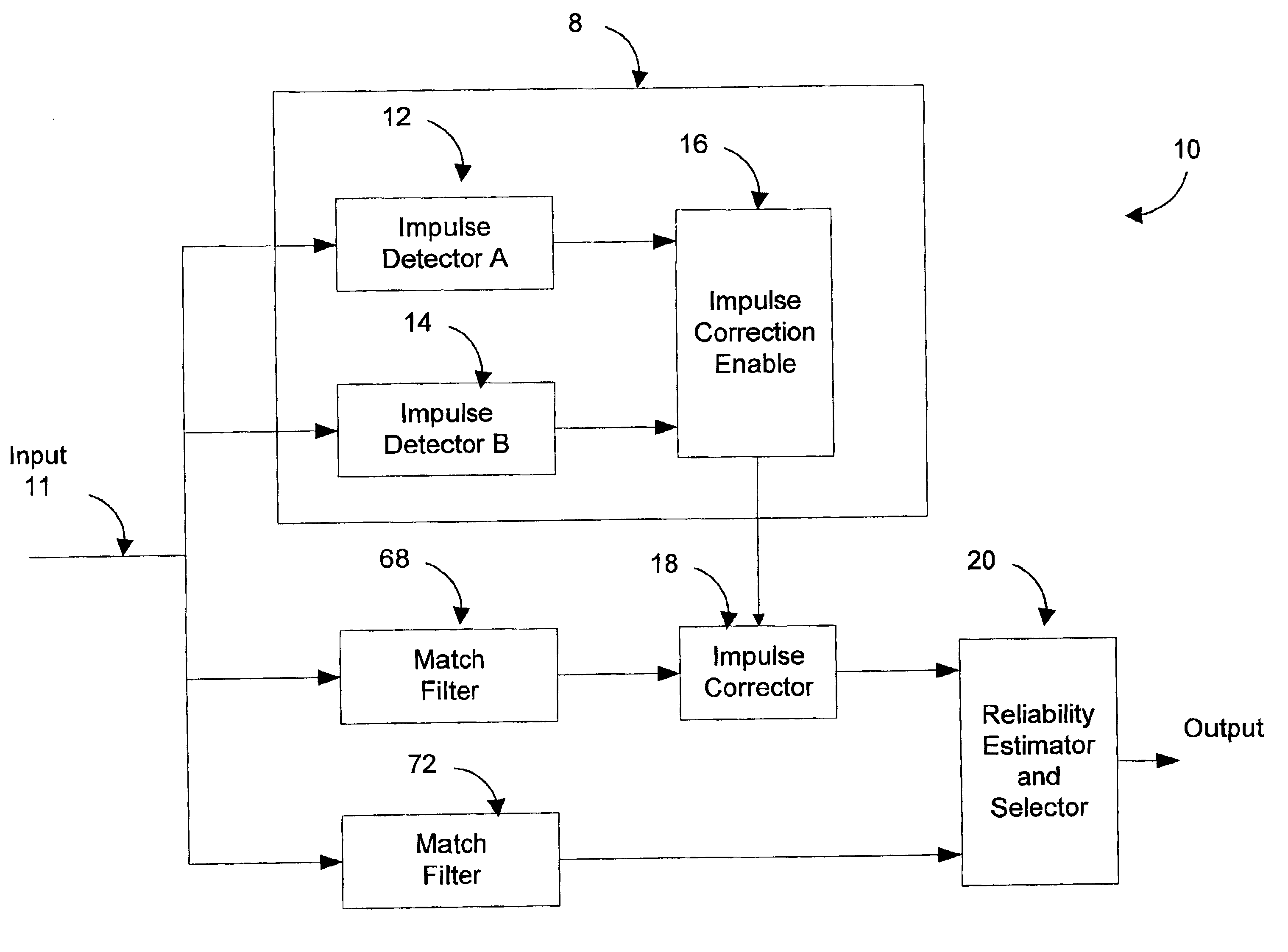
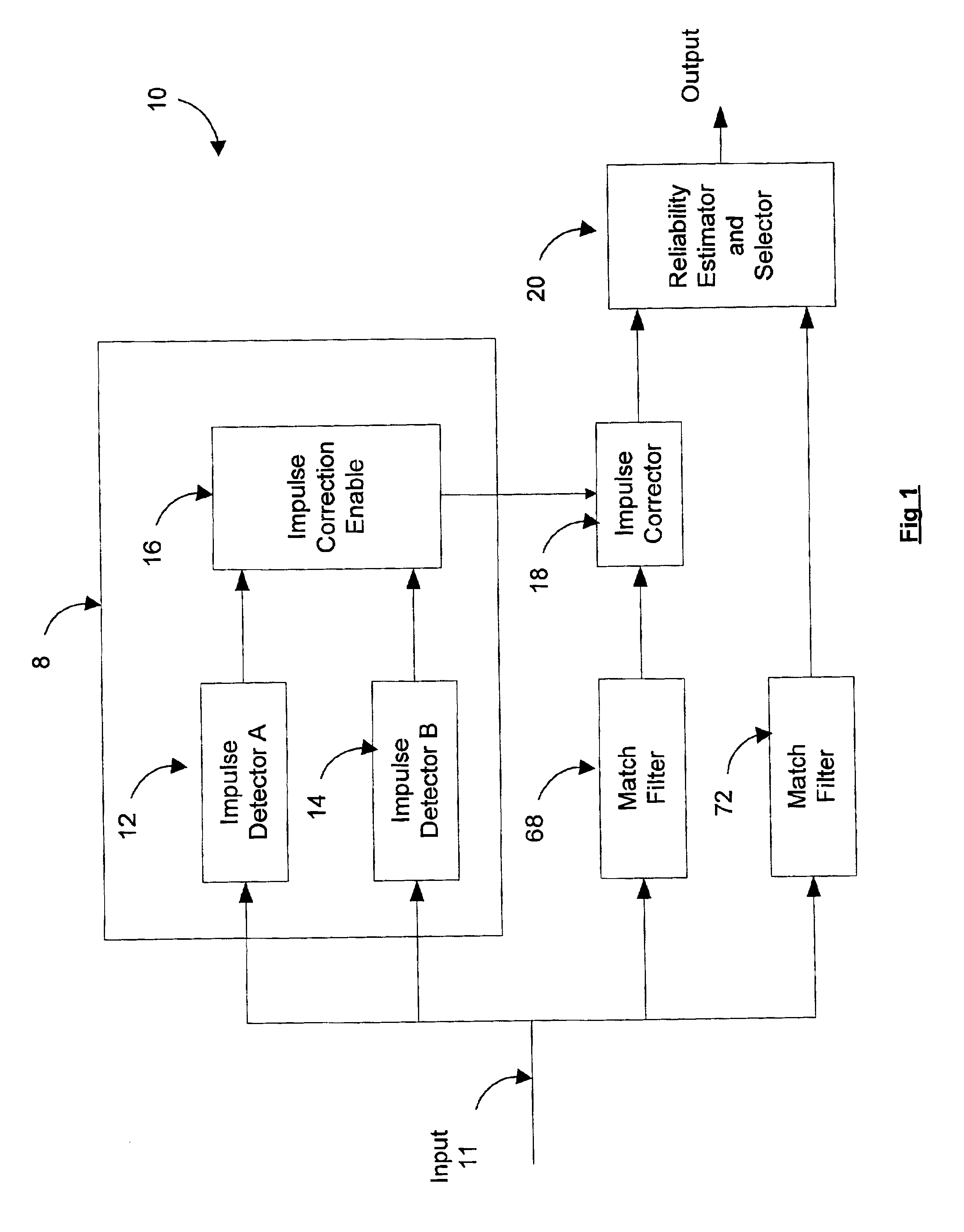
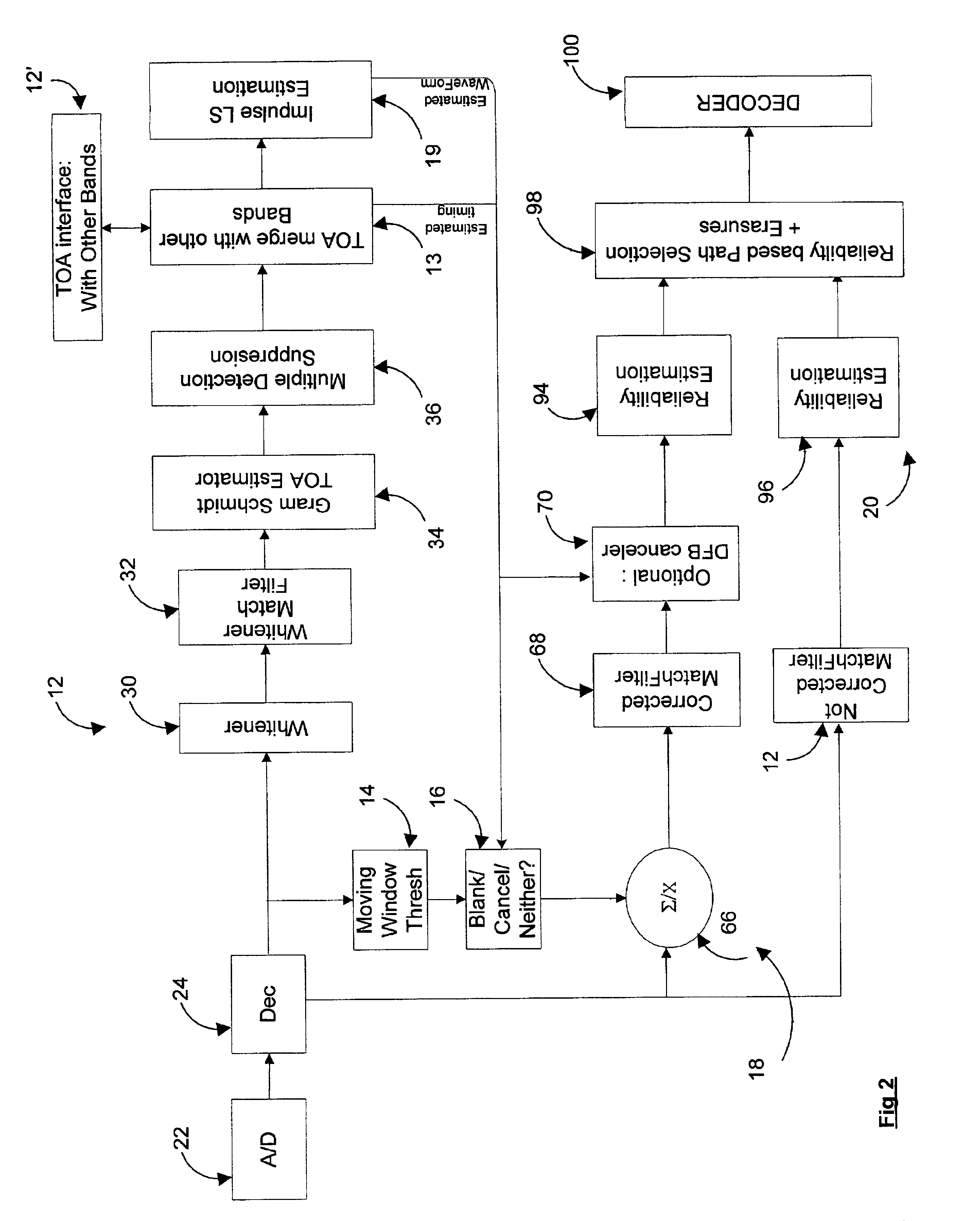
[0029]Turning to FIG. 1, there is shown a block diagram of an impulse detector and corrector system 10 according to the invention. The received input communication signal 11, which can be a single carrier signal or a multi-carrier signal, is input to an impulse detector 8, which preferably comprises two or more separate impulse detectors, 12, 14, each of which uses a different impulse detection scheme. The outputs of the impulse detectors 12, 14 are provided to an impulse correction enable module 16. The signals produced by the impulse detectors 12, 14 indicate when an impulse has been detected and may contain information about the detected impulse itself. The correction enable module 16 uses the information contained in the impulse detection signals to determine when an impulse is present and signals via its output that impulse correction is required.

[0030]In the preferred embodiment, the outputs of two or more separate impulse detectors are used to determine the timing and possibl...


PUM


Abstract

A system for detecting and correcting impulse noise present on an input data signal includes an impulse detector module receiving an input data signal and producing as output an correction enable signal indicating when an impulse correction is required. An impulse corrector module receives the input data signal and a correction enable signal and produces a corrected data signal, e.g., having the impulse canceled or blanked, as output. A reliability estimator and selector module receives the corrected data signal and the input data signal and selects as output the input signal which is more reliable. In one embodiment, the impulse detector includes first and second complementary impulse detectors, the outputs of which are analyzed by an enable and correction module to produce an impulse detection signal with improved accuracy. Preferably, the enable and correction module also indicates the most appropriate type of impulse correction in accordance with the detection signals from the complementary detectors. A novel system and method of detecting impulses based on Gram Schmidt techniques is also presented. In this method, one or more channels of a multi-channel data signal are kept free of data. When a whitening filter is applied, impulses on these quiet channels are emphasized. The Gram Schmidt technique exploits this fact to provide for improved impulse detection. The system can be modified to detect other types of low dimensionality noise.

Description

FIELD OF THE INVENTION[0001]This invention is related generally to receiving apparatus for a data communication system. More particularly, this invention is directed to a method and system for detecting, timing, and correcting impulse noise on a data communication channel.BACKGROUND OF THE INVENTION[0002]Communications systems are used to transfer data between remote transmitting and receiving locations over one or more physical channels. The integrity and reliability of such data transmissions can be compromised by several factors, such as transmission imperfections, receiving imperfections, and physical channel interference. Examples of interference which affect the quality and rate of data transmission include impulses (or bursts), and other short duration events, and long duration interference, such as ingresses. A relatively large effort has been directed to improving the transmitter and receiver robustness for long duration interference. However, compensating for impulse / burst...

Claims


Application Information

Patent Timeline
Patent Type & Authority Patents(United States)
IPC IPC(8): H04L25/06H04L27/26
CPCH04L25/067H04L27/2647
Inventor STOPLER, DANNYZAMIR, RAM
Owner RPX CORP
Why Eureka
Try Eureka