
Method for forming a channel on the surface of a metal substrate

a metal substrate and surface technology, applied in the direction of soldering media, fluid speed measurement, rocket engine plants, etc., can solve problems such as channel formation

Inactive Publication Date: 2005-07-26
GENERAL ELECTRIC CO
View PDF13 Cites 92 Cited by
  • Summary
  • Abstract
  • Description
  • Claims
  • Application Information

AI Technical Summary

Benefits of technology

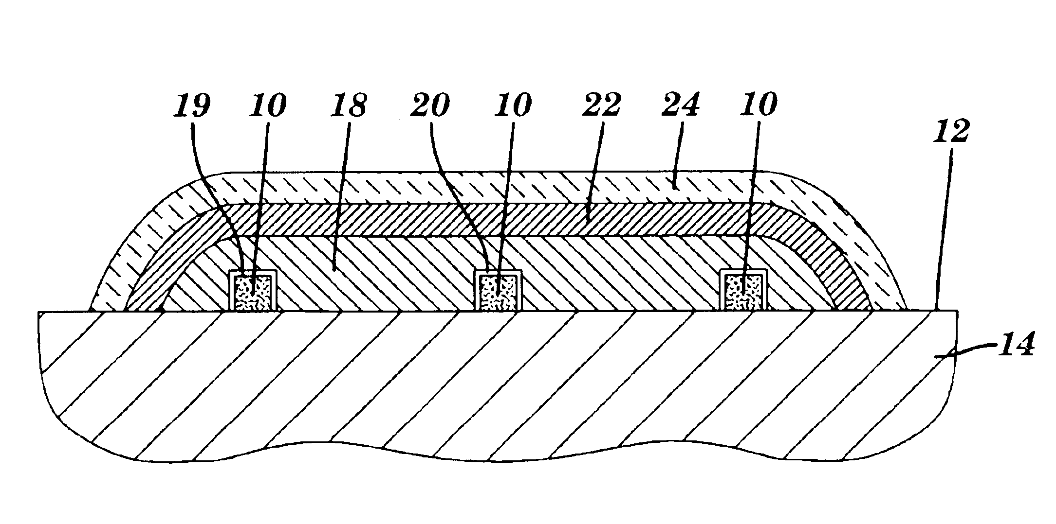
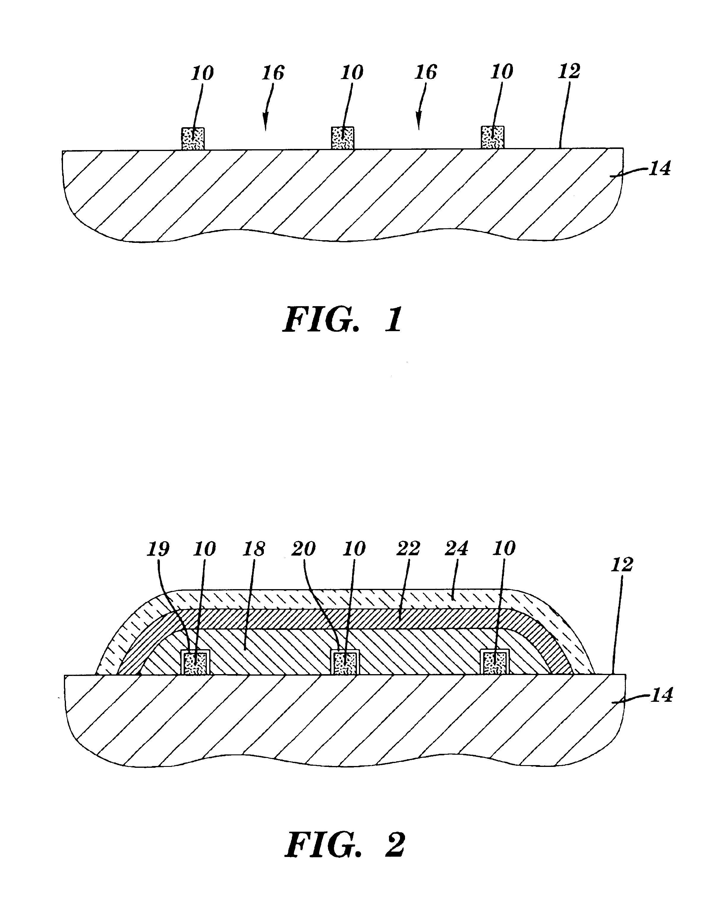
[0014](A) depositing a stop-off material on the surface of the substrate, in a pattern which represents a selected shape for the channel, wherein the stop-off material is capable of preventing adhesion between the substrate and a bonding agent applied over the substrate and the stop-off material; and

Problems solved by technology

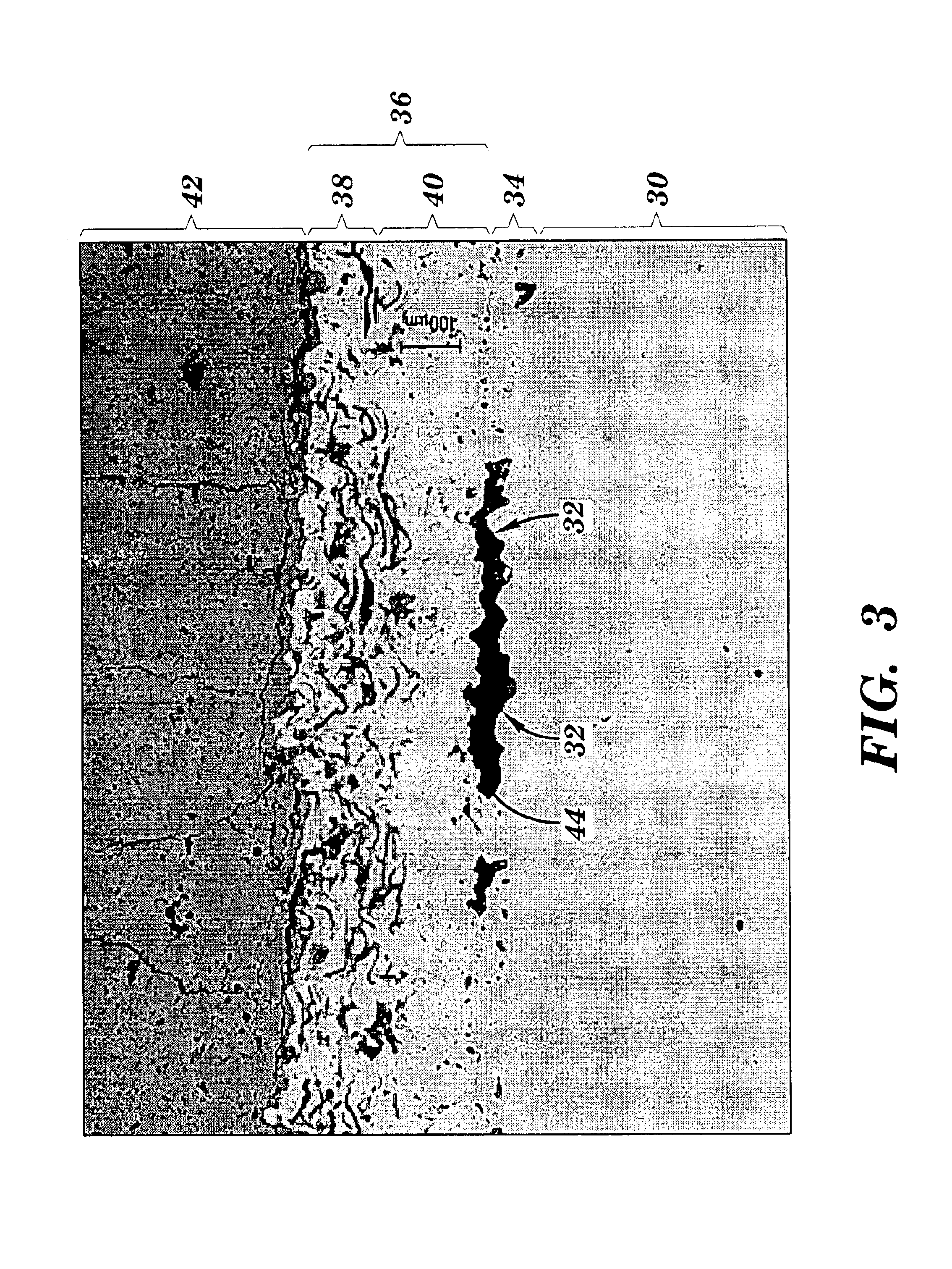
This lack of adhesion or “wetting” also results in the formation of a channel.

Method used


Image

  • Method for forming a channel on the surface of a metal substrate
  • Method for forming a channel on the surface of a metal substrate
  • Method for forming a channel on the surface of a metal substrate

Examples


Embodiment Construction

[0028]The metal-based substrate of this invention can be formed from a variety of metals. The term “metal-based”, as used herein, describes substrates which are primarily formed of metal or metal alloys, but which may also include some non-metallic components. “Non-metallic” refers to materials like ceramics, or intermediate phases. Usually, the substrate is a heat-resistant alloy, e.g., superalloys which typically have an operating temperature of up to about 1000-1150° C. The term “superalloy” is usually intended to embrace complex cobalt-, nickel-, or iron-base alloys which include one or more other elements, such as aluminum, tungsten, molybdenum, and titanium. Superalloys are described in many references. Nickel-base superalloys typically include at least about 40 wt % Ni. Cobalt-base superalloys typically include at least about 30 wt % Co. The actual configuration of a substrate may vary widely. For example, the substrate may be in the form of various turbine engine parts, such...


PUM

PropertyMeasurementUnit
Percent by massaaaaaaaaaa
Depthaaaaaaaaaa
Depthaaaaaaaaaa

Abstract

A method for forming a channel within a coated, metal-based substrate is described. In one technique, a channel-forming material is first deposited on the substrate, followed by the deposition of a bonding agent, such as a braze. One or more coatings can then be applied over the substrate. In one embodiment, the channel is formed when the channel-forming material is subsequently removed. In another embodiment, the channel is formed due to the lack of adhesion between particular channel-forming materials and the overlying bonding agent. Related articles are also described, e.g., gas turbine components which include protective coatings and a pattern of cooling channels.

Description

TECHNICAL FIELD[0001]This invention generally relates to methods for the formation of hollow structures in the surface region of a coated metal substrate. In some specific embodiments, the invention is directed to methods for forming cooling channels at or near the surface of high-temperature articles covered with protective coatings.BACKGROUND OF THE INVENTION[0002]Various types of metals are used for components which may be exposed to a high-temperature environment, such as aircraft engine parts. A variety of approaches have been used to raise the operating temperature at which the metal components can be used. For example, one approach involves the use of protective coatings on various surfaces of the component, e.g., a gas turbine engine airfoil. The coatings are usually ceramic-based, and are sometimes referred to as thermal barrier coatings or “TBC's”.[0003]The TBC's are typically used in conjunction with internal cooling channels within the airfoil, through which cool air is ...

Claims


Application Information

Patent Timeline
IPC IPC(8): B23P15/00C23C26/02C23C4/18C23C28/00C23C26/00C23C4/00F01D5/18F01D5/28F02K9/64F02K9/00F23R3/00B81B1/00F02C7/00
CPCC23C26/02C23C28/3455F01D5/18F01D5/288F02K9/64F23R3/002F23R3/005B23P15/008B81B1/00C23C4/005C23C4/18C23C26/00C23C28/3215Y10T29/49341Y02T50/67Y10T29/49321Y10T29/49812C23C4/01C23C28/00Y02T50/60
Inventor HASZ, WAYNE CHARLESVENKATARAMANI, VENKAT S.LEE, CHING-PANG
Owner GENERAL ELECTRIC CO
Learn More