Substrate positioning system

a positioning system and substrate technology, applied in the field of positioning mechanisms, can solve the problems of adding additional complexity of motion, and achieve the effects of convenient use, efficient and accurate movement of substrates, and convenient processing

Inactive Publication Date: 2005-07-26
AXCELIS TECHNOLOGIES
View PDF2 Cites 1 Cited by
  • Summary
  • Abstract
  • Description
  • Claims
  • Application Information

AI Technical Summary

Benefits of technology

[0007]It is a feature of the present invention to provide a substrate positioning system to facilitate the performing of certain processing on the substrate, such as ion implantation. It is another feature to provide such a system with rotatable members synchronized to form a robotic unit to efficiently and accurately move the substrate to a desired range of motion. It is yet another feature to provide such a system with a base movable linearly along an axis such that the system maintains a constant distance of travel for an ion beam incident on the substrate as the rotatable members travel in a curved path. It is yet another feature of the present invention to provide such a system where the rotatable members simultaneously rotate to maintain a substantially constant incident angle of the substrate relative to the ion beam. It is yet another feature of the present invention to provide such a system that is easy to use, simple in operation, and particularly well suited for the proposed usages thereof.

Problems solved by technology

The mechanical scan is necessary due to the difficulty of electrically scanning the beam over a large area of the substrate while keeping the angle of incidence of the beam to the substrate surface constant.
This device requires the coordination of three rotary axes to maintain the angle of incidence at a constant value as the wafer is scanned, thus adding additional complexity of motion.

Method used


Image

  • Substrate positioning system
  • Substrate positioning system
  • Substrate positioning system

Examples


Embodiment Construction

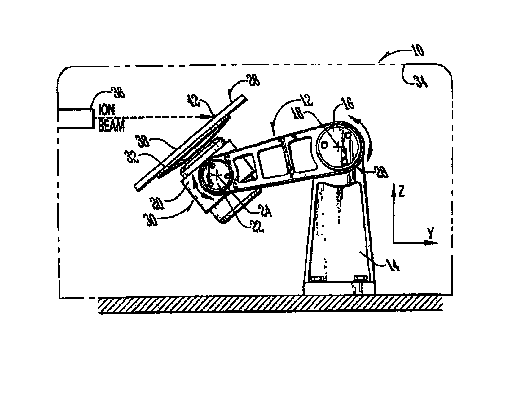
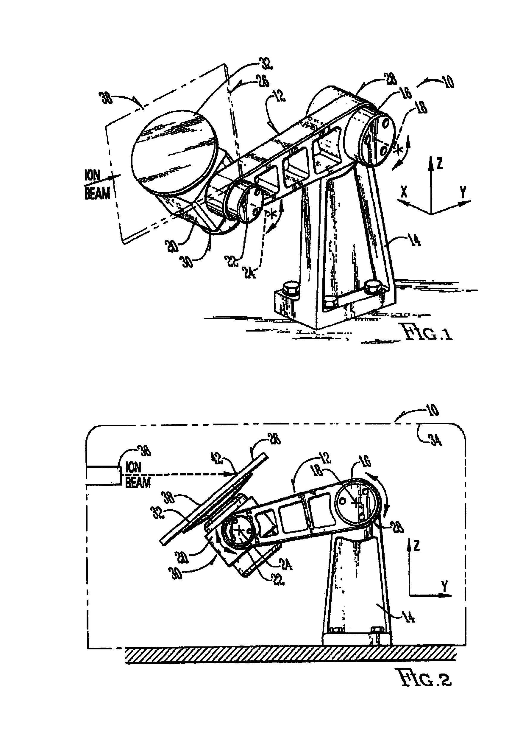
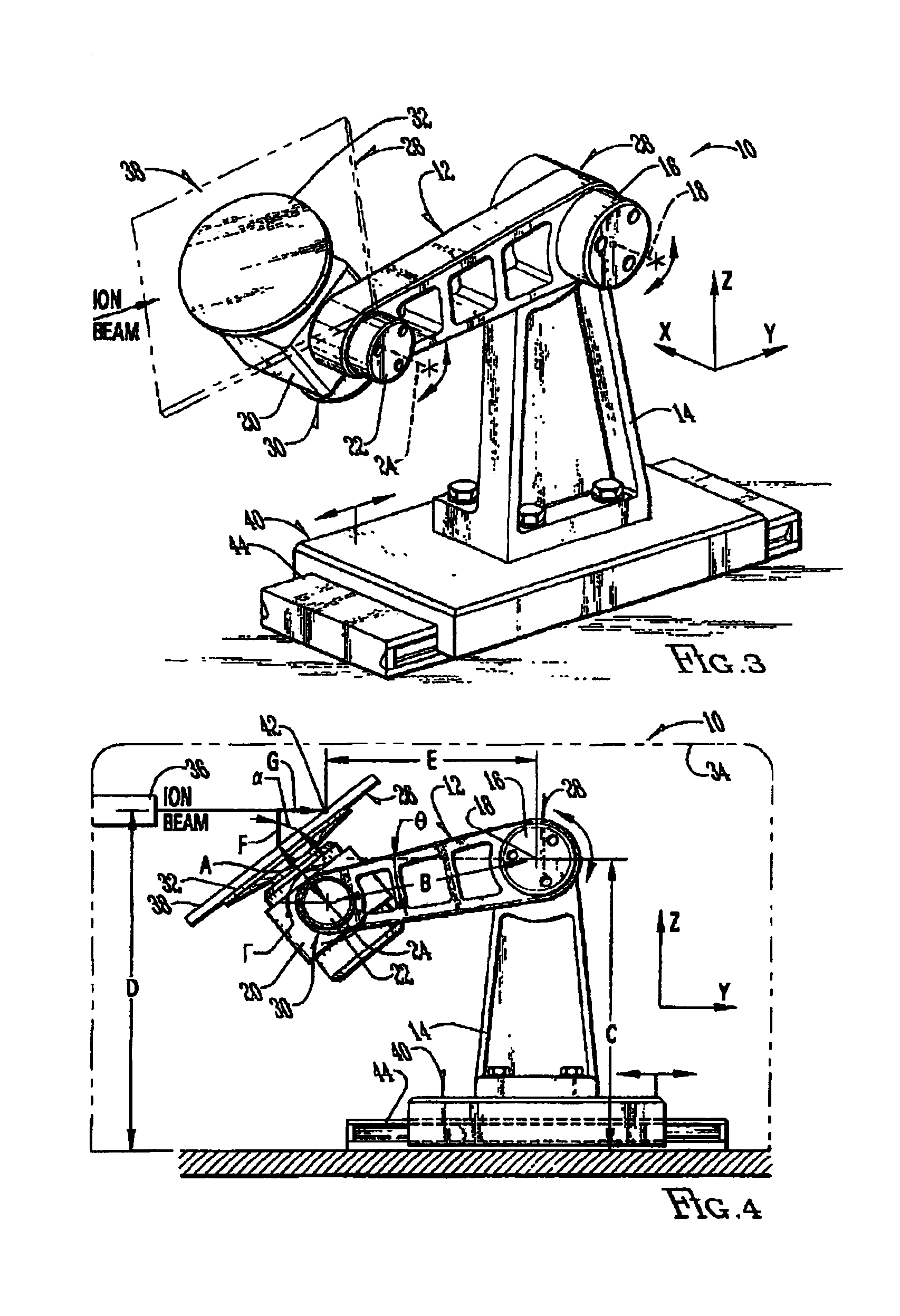
[0015]The substrate positioning system 10 of the present invention is shown generally in FIGS. 1 and 2. The system 10 provides a linkage 12 rotatably mounted to a base 14 with a first rotary joint 16 at a first rotary axis 18 and an end effector member 20 rotatably mounted to the linkage 12 with a second rotary joint 22 at a second rotary axis 24 for properly positioning a substrate 26 for various processing. The first rotary axis 18 is located at a proximal end 28 of the linkage 12 and the second rotary axis 24 is located at a distal end 30 of the linkage 12. Both axes are aligned in parallel relationship to one another and extend generally parallel to the x-axis. Thus, the base 14 extends upward along the z-axis and the linkage 12 and end effector member 20 generally move in the y-z plane. Through the synchronized rotation of the linkage 12 about the base 14 and the end effector member 20 about the linkage 12, the system 10 acts as a robotic unit to move the substrate 26 to the de...


PUM


Abstract

A substrate positioning system is provided to facilitate the performing of certain processing on the substrate, such as ion implantation. The system comprises a linkage rotatably mounted to a base and an end effector member rotatably mounted to the linkage and configured for receiving a substrate. Through the synchronized rotation of the linkage about the base and the end effector member about the linkage, the system acts as a robotic unit to move the substrate to the desired location for performing processing thereon. In another aspect, the base is movable along an axis such that the system maintains a constant distance of travel for an ion beam incident on the substrate as the linkage and end effector member travel in a curved path.

Description

RELATED APPLICATIONS[0001]This application is a continuation of U.S. patent application Ser. No. 10 / 153,114, filed May 21, 2002 U.S. Pat. No. 6,777,687, entitled “SUBSTRATE POSITIONING SYSTEM”, which is a continuation of U.S. patent application Ser. No. 10 / 081,610, filed Feb. 20, 2002 abandoned, entitled “SUBSTRATE POSITIONING SYSTEM”, which claims priority to U.S. provisional patent application Ser. No. 60 / 270,644, filed Feb. 20, 2001, entitled “ROBUST MECHANICAL SCAN ROBOT FOR AN ION IMPLANTER WITH A SINGLE ROTARY LINKAGE”, incorporated herein by reference.BACKGROUND OF THE INVENTION[0002]This invention relates generally to positioning mechanisms, and more particularly, to a substrate positioning system facilitating the performing of certain processing on the substrate, such as ion implantation.DESCRIPTION OF RELATED ART[0003]Robotic units and other positioning mechanisms are known for performing certain controlled tasks. With respect to mechanisms for assisting in ion implantatio...

Claims


Application Information

Patent Timeline
Patent Type & Authority Patents(United States)
IPC IPC(8): H01L21/67G21K5/10H01L21/68H01J37/317H01L21/687
CPCH01J37/3171H01L21/68H01L21/68764H01J2237/20
Inventor VANDERPOT, JOHN W.BERRIAN, DONALD W.POLLOCK, JOHN D.
Owner AXCELIS TECHNOLOGIES
Why Eureka
Try Eureka