
Generating arbitrary passive beam forming networks

Inactive Publication Date: 2005-07-26
KATHEIN WERKE KG
View PDF12 Cites 16 Cited by
  • Summary
  • Abstract
  • Description
  • Claims
  • Application Information

AI Technical Summary

Benefits of technology

[0009]The present invention is directed to systems and methods which apply design criteria to beam forming network parameters to consistently arrive at a passive beam forming network design. Preferably such passive beam forming network designs are arrived at without design input from a highly skilled individual, such as an RF engineer. Accordingly, embodiments of the present invention may be substantially automated, thereby facilitating the efficient and rapid design and / or manufacture of complex passive beam forming networks.
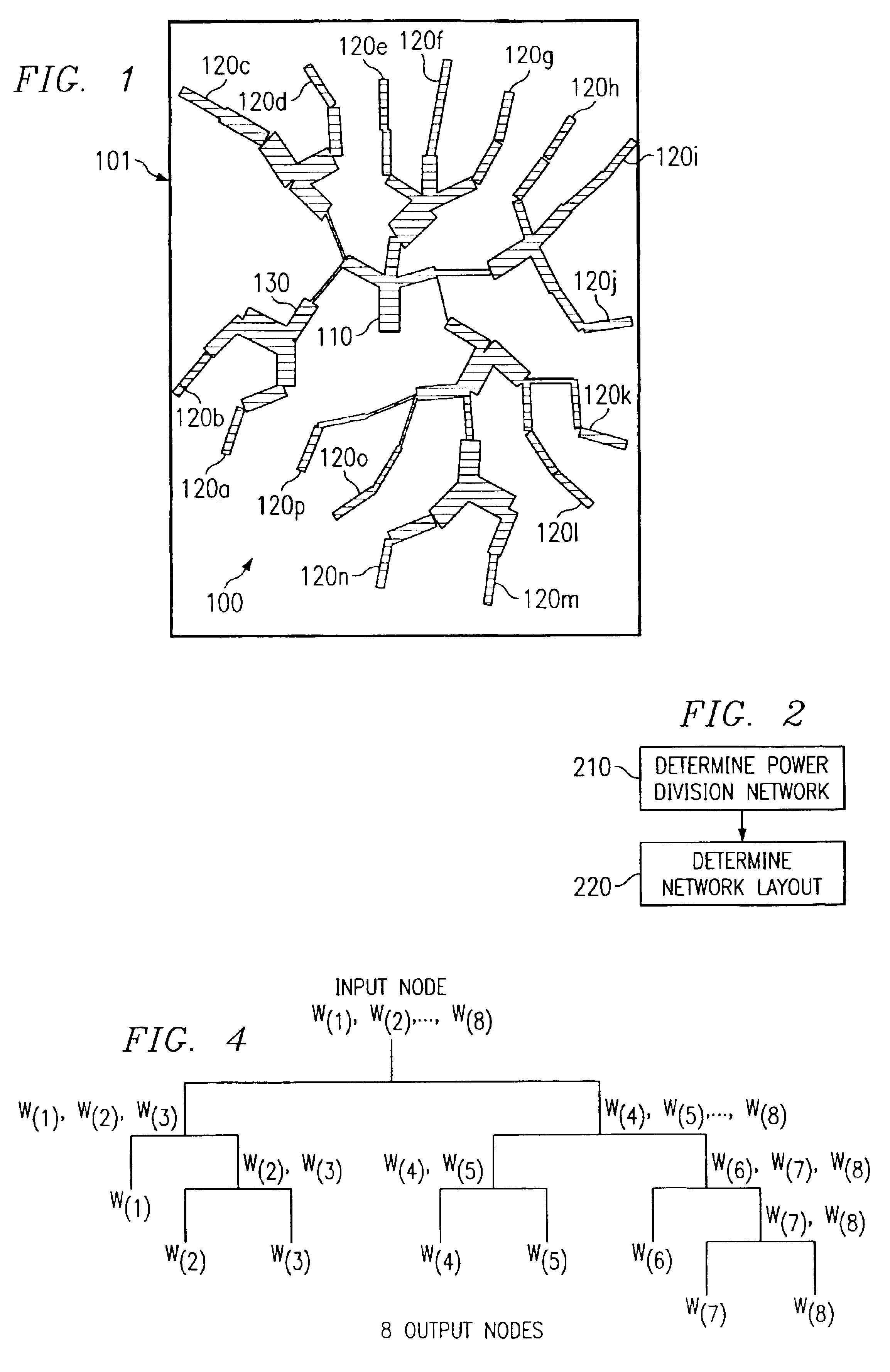
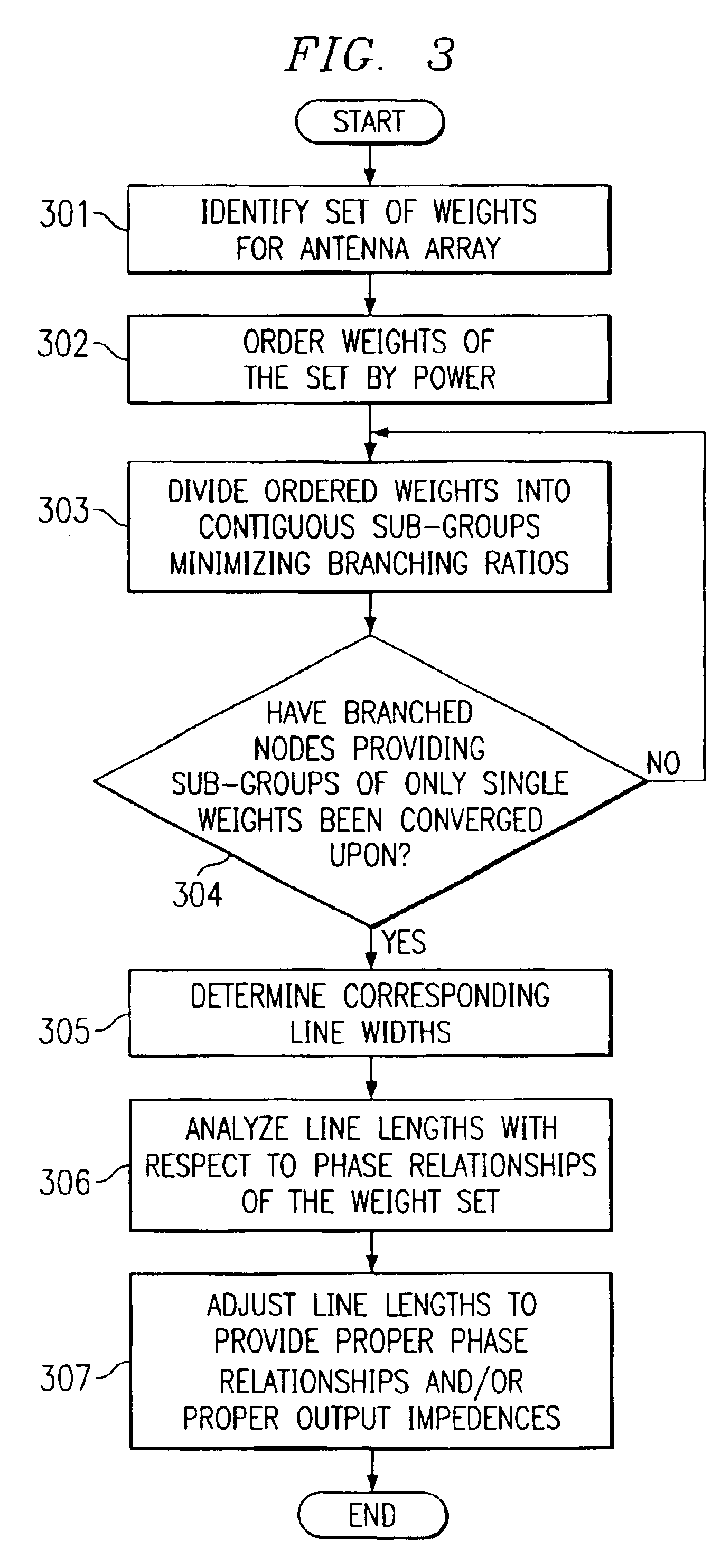
[0011]According to a preferred embodiment, a passive beam forming network is comprised of a number of microstrip or stripline feed paths disposed in a tree-like structure, wherein branching nodes of the tree-like structure provide power division / combining. For example, the microstrip line widths of each such branch of a branching node may determine the ratio of power splitting / combining among the branches of the branching node. Accordingly, operation of the aforementioned first primary stage may provide a branching configuration which determines how the weights of a desired radiation pattern weight set are allocated in the beam forming network. For example, a passive beam forming network may be designed in which one input is divided into multiple branches at a first node, each of those branches again divided into multiple branches at subsequent nodes, and so on. In this way, a network may be designed with one input and an arbitrary number of outputs, such as a number of outputs corresponding to antenna elements or element arrays in a phased array antenna structure.

Problems solved by technology

In the past, designing complex beam forming networks has required the talents of a skilled radio frequency (RF) engineer and, typically, many hours of design time.
This could be a lengthy process, on the order of a few days.
If it were desired to generate many beam forming networks, such a process would require many RF engineers and / or considerable lead time.
Such an approach, in addition to being an expensive proposition, does not readily facilitate the manufacture of a large number of such passive beam forming networks, such as for providing unique radiation patterns throughout a communication network and / or to provide reconfigured beam forming networks in response to topology and morphology changes in the network.

Method used


Image

  • Generating arbitrary passive beam forming networks
  • Generating arbitrary passive beam forming networks
  • Generating arbitrary passive beam forming networks

Examples


Embodiment Construction

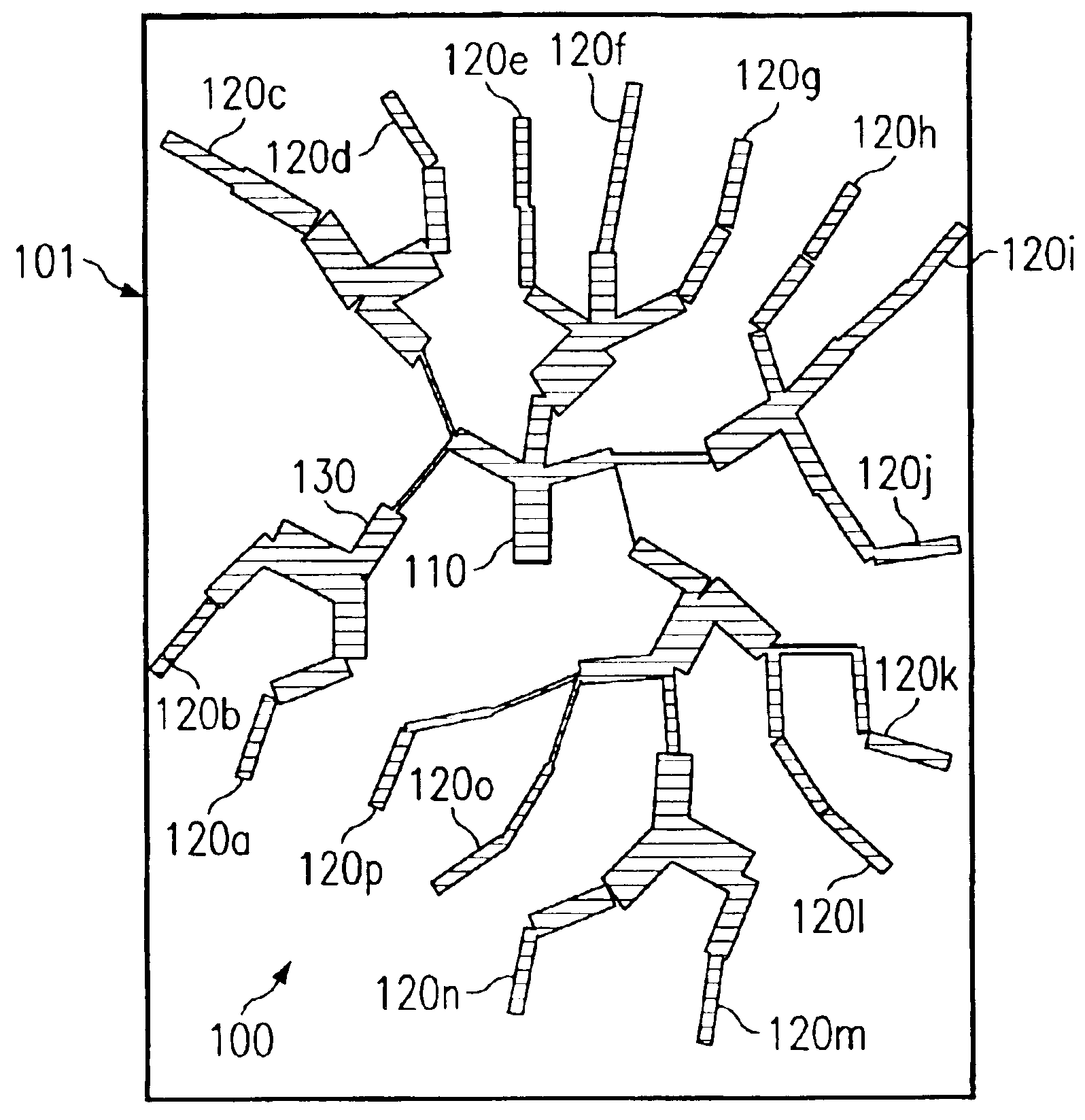
[0027]Providing radiation pattern shaping, such as shown in the above referenced patent applications entitled “Passive Shapable Sectorization for Cellular Networks” and “Passive Shapable Sectorization Antenna Gain Determination,” may utilize a passive beam forming network that produces a fixed number of RF outputs (e.g., 8, 12, 16, etc.) with specified complex weights (gains and phases), corresponding to the excitation signals fed to antenna element columns of an antenna array. Such a passive beam forming network may be implemented by etching a series of microstrip lines on a PCB board, referred to herein as a “personality card”. FIG. 1 shows an illustrative embodiment of board 101 having passive beam forming network 100 of the present invention disposed thereon.

[0028]The aforementioned weights are preferably derived from the desired antenna radiation pattern and a personality card of the present invention may instantiate the weights by dividing the power input at an input node (e.g...


PUM


Abstract

Disclosed are systems and methods which apply design criteria to beam forming network parameters to arrive at a passive beam forming network design. Preferably a beam forming network approach is implemented in two primary stages. Operation of the aforementioned first primary stage may provide a branching configuration which determines how the weights of a desired radiation pattern weight set are allocated in the beam forming network. Preferably, branching nodes are configured to substantially equally distribute power splitting / combining the branches of a node. The aforementioned second primary stage operates to determine the actual physical layout of the various components. Preferably, each branching node is analyzed to determine an optimal physical layout configuration with respect thereto.

Description

CROSS-REFERENCE TO RELATED APPLICATIONS[0001]The present application is related to, and hereby claims priority to, co-pending and commonly assigned U.S. provisional patent applications Ser. No. 60 / 322,573 entitled “Co-Located Antenna Array for Passive Beam Forming,” filed Sep. 12, 2001, Ser. No. 60 / 322,542 entitled “Automated Process for Generating Arbitrary Passive Beam Forming Networks,” filed Sep. 12, 2001, Ser. No. 60 / 322,494 entitled “Inexpensive Fabrication Technique for Making Antenna Element Cards,” filed Sep. 12, 2001, and Ser. No. 60 / 342,571 entitled “Co-Located Antenna Array for Passive Beam Forming,” filed Dec. 20, 2001, the disclosures of which are incorporated herein by reference in their entirety. The present application is also copending and related to commonly assigned U.S. patent applications Ser. No. 10 / 242,276 entitled “Co-Located Antenna Array for Passive Beam Forming,” concurrently filed herewith, Ser. No. 09 / 878,599 entitled “Passive Shapable Sectorization for...

Claims


Application Information

Patent Timeline
IPC IPC(8): H01Q9/04H01Q9/28H01Q21/06H01Q21/30H01Q21/28H01Q1/24H01Q21/00
CPCH01Q1/246H01Q9/28H01Q21/0006H01Q21/0075H01Q21/061H01Q21/28H01Q21/30
Inventor GORDON, SCOT D.KAPLAN, MITCH S.
Owner KATHEIN WERKE KG
Learn More