Thin-film magnetic head and method of manufacturing same

a thin-film magnetic head and manufacturing method technology, applied in the direction of metal sheet core heads, instruments, nanoinformatics, etc., can solve the problems of difficult to increase the linear recording density, one of the thin-film magnetic heads disclosed in the aforementioned publications is vulnerable to curving at the edge opposite to the gap portion of the magnetic pole portion, etc., to improve the high-frequency characteristics, reduce the length of the magnetic path, and increase the intensity of the magnetic field

Inactive Publication Date: 2005-07-26
TDK CORPARATION
View PDF14 Cites 20 Cited by
  • Summary
  • Abstract
  • Description
  • Claims
  • Application Information

AI Technical Summary

Benefits of technology

[0020]It is therefore an object of the present invention to provide a thin-film magnetic head and a method of manufacturing same, which make it possible to increase the intensity of magnetic field generated from the magnetic pole portion in the direction perpendicular to the surface of the recording medium, and to reduce a magnetic path length to improve high-frequency characteristics.
[0030]In the first thin-film magnetic head of the invention, the second magnetic layer has the pole portion layer and the yoke portion layer. A surface of the at least part of the thin-film coil, the surface being closer to the second magnetic layer, is located closer to the first magnetic layer than an end of the gap layer is, the end being located in the medium facing surface next to the second magnetic layer. The yoke portion layer is magnetically connected to the pole portion layer at least at a surface of the pole portion layer that is closer to the gap layer, and both side surfaces of the pole portion layer in the width direction. Accordingly, the invention allows the yoke portion layer to form a short magnetic path between a portion thereof magnetically coupled to the first magnetic layer and the pole portion layer, and allows the yoke portion layer to be disposed close to the thin-film coil. Further, in the invention, since the pole portion layer has a saturated magnetic flux density equal to or greater than that of the yoke portion layer, and the yoke portion layer is magnetically connected to the pole portion layer at least at a surface of the pole portion layer closer to the gap layer and at both side surfaces of the pole portion layer in the width direction, it is possible to prevent a magnetic flux from being saturated halfway through the second magnetic layer. Consequently, the invention makes it possible to improve electromagnetic conversion efficiency, to increase the intensity of the magnetic field generated from the magnetic pole portion in the direction perpendicular to the surface of the recording medium, and to reduce a magnetic path length, thereby improving high-frequency characteristics.
[0046]In the first method of manufacturing a thin-film magnetic head of the invention, the second magnetic layer has the pole portion layer and the yoke portion layer. A surface of the at least part of the thin-film coil, the surface being closer to the second magnetic layer, is located closer to the first magnetic layer than an end of the gap layer is, the end being located in the medium facing surface next to the second magnetic layer. The yoke portion layer is magnetically connected to the pole portion layer at least at a surface of the pole portion layer that is closer to the gap layer, and both side surfaces of the pole portion layer in the width direction. Accordingly, the invention allows the yoke portion layer to form a short magnetic path between a portion thereof magnetically coupled to the first magnetic layer and the pole portion layer, and allows the yoke portion layer to be disposed close to the thin-film coil. Further, in the invention, since the pole portion layer has a saturated magnetic flux density equal to or greater than that of the yoke portion layer, and the yoke portion layer is magnetically connected to the pole portion layer at least at a surface of the pole portion layer closer to the gap layer and at both side surfaces of the pole portion layer in the width direction, it is possible to prevent a magnetic flux from being saturated halfway through the second magnetic layer. Consequently, the invention makes it possible to improve electromagnetic conversion efficiency, to increase the intensity of the magnetic field generated from the magnetic pole portion in the direction perpendicular to the surface of the recording medium, and to reduce a magnetic path length, thereby improving high-frequency characteristics.
[0069]In the second thin-film magnetic head of the invention, the second magnetic layer has the pole portion layer and the yoke portion layer. A surface of the at least part of the thin-film coil, the surface being closer to the second magnetic layer, is located closer to the first magnetic layer than an end of the gap layer is, the end being located in the medium facing surface next to the second magnetic layer. The yoke portion layer is magnetically connected to the pole portion layer at least at a surface of the pole portion layer that is closer to the gap layer, and, a portion where the yoke portion layer and the pole portion layer are connected to each other is located closer to the medium facing surface than a portion where the first magnetic layer and the yoke portion layer are connected to each other. Accordingly, the invention allows the yoke portion layer to form a short magnetic path between a portion thereof magnetically coupled to the first magnetic layer and the pole portion layer, and allows the yoke portion layer to be disposed close to the thin-film coil. Further, in the invention, since the pole portion layer has a saturated magnetic flux density equal to or greater than that of the yoke portion layer, and the yoke portion layer is magnetically connected to the pole portion layer at least at a surface of the pole portion layer closer to the gap layer, it is possible to prevent a magnetic flux from being saturated halfway through the second magnetic layer. Consequently, the invention makes it possible to improve electromagnetic conversion efficiency, to increase the intensity of the magnetic field generated from the magnetic pole portion in the direction perpendicular to the surface of the recording medium, and to reduce a magnetic path length, thereby improving high-frequency characteristics.
[0085]In the second method of manufacturing a thin-film magnetic head of the invention, the second magnetic layer has the pole portion layer and the yoke portion layer. A surface of the at least part of the thin-film coil, the surface being closer to the second magnetic layer, is located closer to the first magnetic layer than an end of the gap layer is, the end being located in the medium facing surface next to the second magnetic layer. The yoke portion layer is magnetically connected to the pole portion layer at least at a surface of the pole portion layer that is closer to the gap layer, and, a portion where the yoke portion layer and the pole portion layer are connected to each other is located closer to the medium facing surface than a portion where the first magnetic layer and the yoke portion layer are connected to each other. Accordingly, the invention allows the yoke portion layer to form a short magnetic path between a portion thereof magnetically coupled to the first magnetic layer and the pole portion layer, and allows the yoke portion layer to be disposed close to the thin-film coil. Further, in the invention, since the pole portion layer has a saturated magnetic flux density equal to or greater than that of the yoke portion layer, and the yoke portion layer is magnetically connected to the pole portion layer at least at a surface of the pole portion layer closer to the gap layer, it is possible to prevent a magnetic flux from being saturated halfway through the second magnetic layer. Consequently, the invention makes it possible to improve electromagnetic conversion efficiency, to increase the intensity of the magnetic field generated from the magnetic pole portion in the direction perpendicular to the surface of the recording medium, and to reduce a magnetic path length, thereby improving high-frequency characteristics.

Problems solved by technology

However, such a thin-film magnetic head has not been realized that is suitable for the vertical magnetic recording scheme and has characteristics capable of realizing a magnetic read / write apparatus having an areal recording density of 60G bits / inch2 or greater.
This is because of problems as discussed below that are present in the prior-art thin-film magnetic heads.
First, any one of the thin-film magnetic heads disclosed in the aforementioned publications is intended structurally for the longitudinal magnetic recording scheme and not suitable for the vertical magnetic recording scheme.
This structure raises a problem that the magnetic pole portion develops a reduced magnetic field that is perpendicular to the surface of the recording medium.
Furthermore, any one of the thin-film magnetic heads disclosed in the aforementioned publications is vulnerable to curving at the edge opposite to the gap portion of the magnetic pole portion, due to the etching for patterning the magnetic pole portion of the second magnetic layer or the steps subsequent to the formation of the magnetic pole portion.
This raises a problem that a distortion occurs in the shape of the bit pattern of the recording medium, which makes it difficult to increase the linear recording density.
Furthermore, any one of the thin-film magnetic heads disclosed in the aforementioned publications has a structure in which the yoke portion is arranged so as to detour around the coil, which raises a problem of having a long magnetic path, and this in turn causes a deterioration of the high-frequency characteristics.
Accordingly, this raises a problem that the magnetic flux is saturated at the connecting portion, thereby causing the magnetic pole portion to generate a reduced magnetic field in the medium facing surface.
Accordingly, this raises a problem that the magnetic flux tends to be saturated halfway through the magnetic layer and therefore the main magnetic pole generates a reduced magnetic field in the medium facing surface.
Such a structure makes the head inefficient in terms of the intensity of magnetic field and high-frequency characteristics.

Method used


Image

  • Thin-film magnetic head and method of manufacturing same
  • Thin-film magnetic head and method of manufacturing same
  • Thin-film magnetic head and method of manufacturing same

Examples


first embodiment

[First Embodiment]

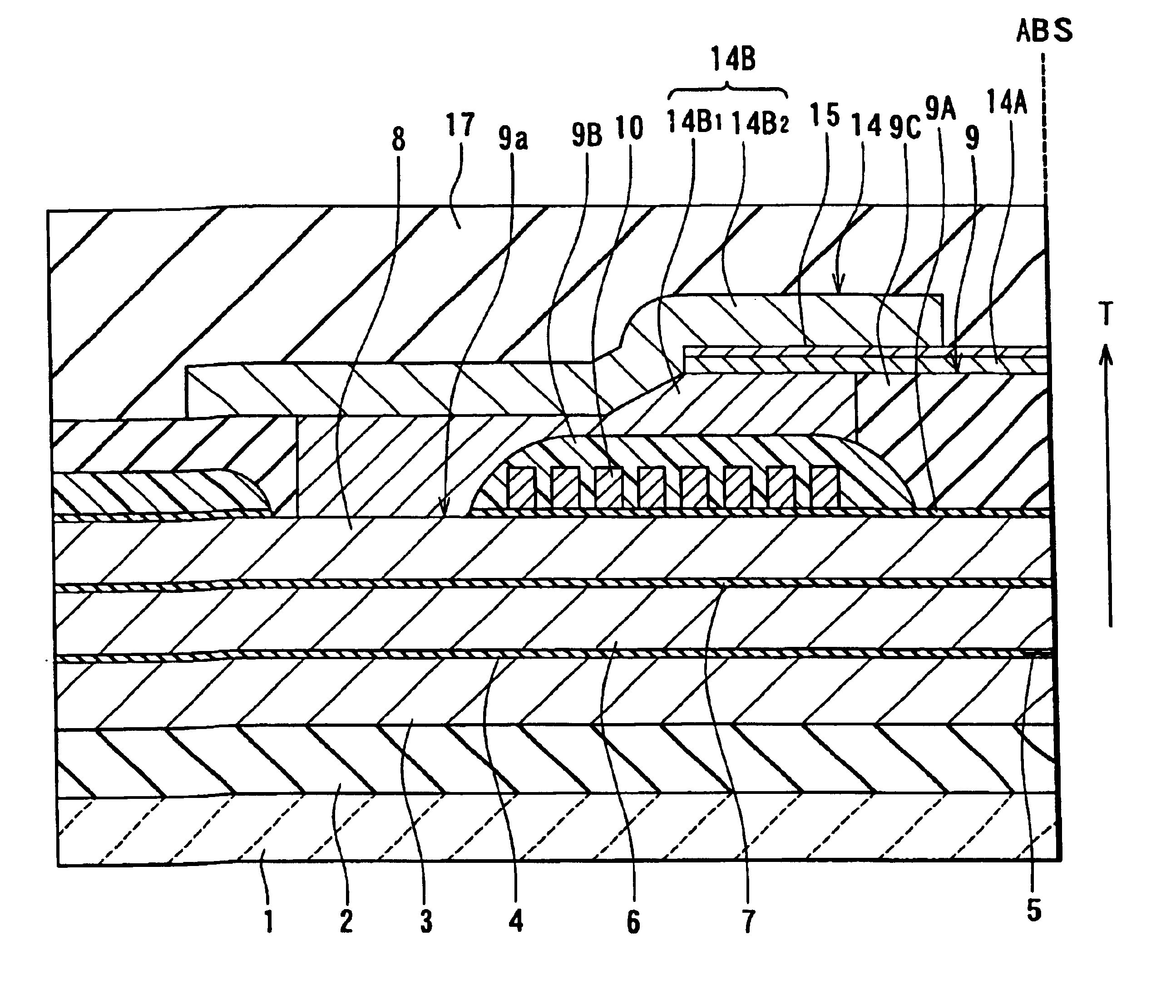
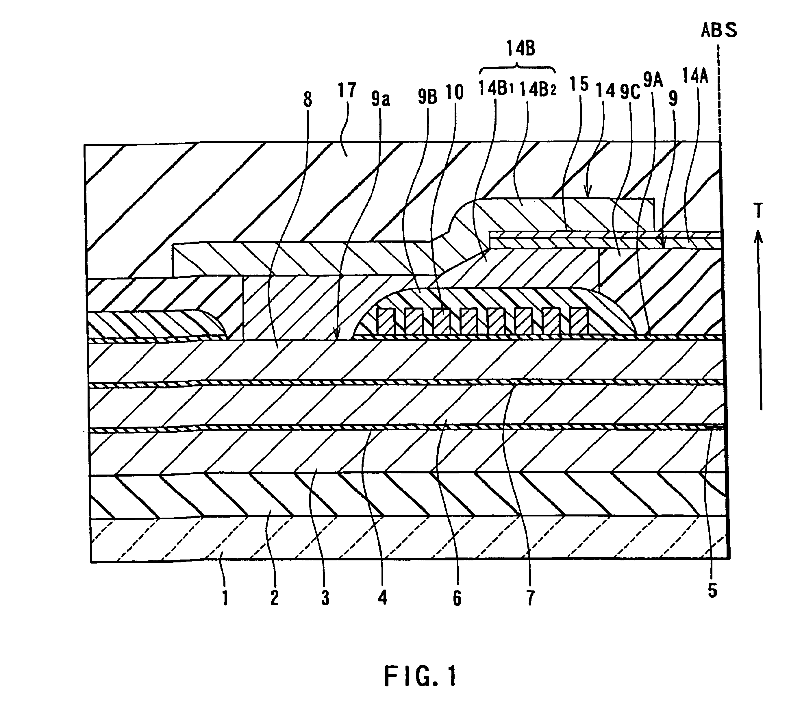
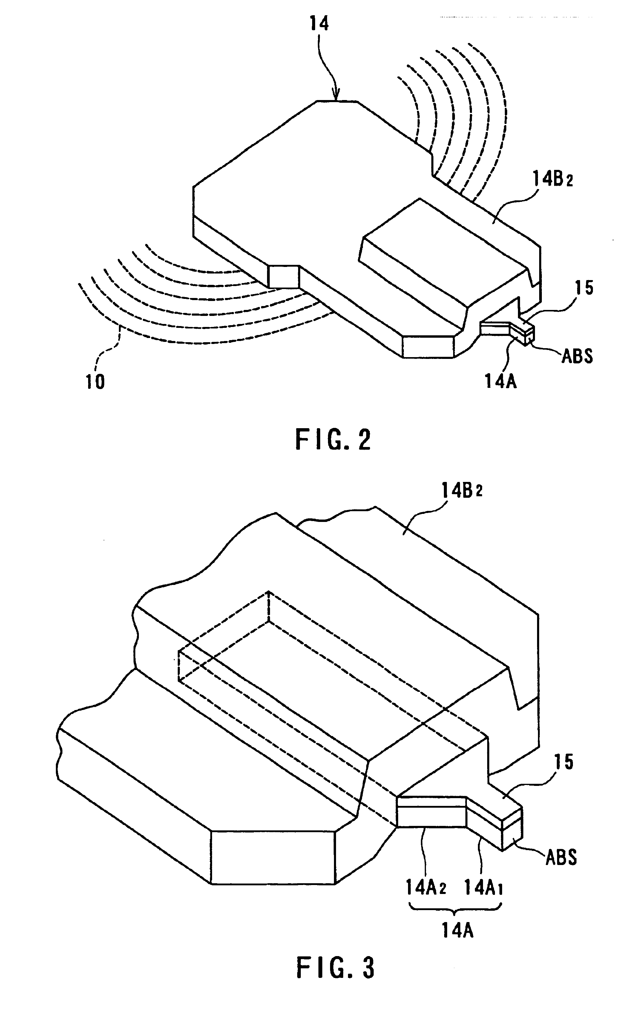
[0138]A thin-film magnetic head according to a first embodiment of the invention will now be explained with reference to FIGS. 1 to 5. FIG. 1 is a cross-sectional view illustrating the structure of the thin-film magnetic head of this embodiment. FIG. 1 shows a cross section orthogonal to the medium facing surface and the surface of the substrate. In addition, the arrow indicated by symbol T in FIG. 1 shows the traveling direction of a recording medium. FIG. 2 is a perspective view illustrating the main part of the thin-film magnetic head shown in FIG. 1. FIG. 3 is an enlarged perspective view illustrating the vicinity of the magnetic pole portion shown in FIG. 2. FIG. 4 is a front view illustrating part of the medium facing surface of the thin-film magnetic head shown in FIG. 1. FIG. 5 is an enlarged front view illustrating the pole portion layer and the non-magnetic layer shown in FIG. 4.

[0139]As shown in FIG. 1, the thin-film magnetic head of this embodiment comp...

second embodiment

[Second Embodiment]

[0222]A thin-film magnetic head according to a second embodiment of the invention will now be explained with reference to FIGS. 23 and 24. FIG. 23 is a cross-sectional view illustrating the structure of the thin-film magnetic head of this embodiment. FIG. 23 shows a cross section orthogonal to the medium facing surface and the surface of the substrate. In addition, the arrow indicated by symbol T in FIG. 23 shows the traveling direction of a recording medium. FIG. 24 is a perspective view illustrating the main part of the thin-film magnetic head shown in FIG. 23.

[0223]In this embodiment, the first layer 14B1 of the yoke portion layer 14B is smaller in thickness than in the first embodiment. The thickness of the first layer 14B1 at the position of the contact hole 9a is equal to or less than the total thickness of the insulating layers 9A, 9B. The first layer 14B1 preferably has a thickness of 1 μm or more at the position of the contact hole 9a.

[0224]In this embod...

third embodiment

[Third Embodiment]

[0243]A thin-film magnetic head according to a third embodiment of the invention will now be explained with reference to FIGS. 37 to 38. FIG. 37 is a cross-sectional view illustrating the structure of the thin-film magnetic head of this embodiment. FIG. 37 shows a cross section orthogonal to the medium facing surface and the surface of the substrate. In addition, the arrow indicated by symbol T in FIG. 37 shows the traveling direction of a recording medium. FIG. 38 is a perspective view illustrating the main part of the thin-film magnetic head shown in FIG. 37.

[0244]In this embodiment, the top surfaces of the first layer 14B1 of the yoke portion layer 14B and the gap layer 9 are flattened together so as to form one plane. In this embodiment, the pole portion layer 14A is formed on the flattened first layer 14B1 and gap layer 9, and the non-magnetic layer 15 is formed on the pole portion layer 14A. In this embodiment, the end of each of the pole portion layer 14A an...


PUM

PropertyMeasurementUnit
distanceaaaaaaaaaa
thicknessaaaaaaaaaa
thicknessaaaaaaaaaa

Abstract

A thin-film magnetic head comprises: a first magnetic layer and a second magnetic layer each of which includes a magnetic pole portion, the first and second magnetic layers being magnetically coupled to each other at a distance from the medium facing surface ABS; a gap layer provided between the first and second magnetic layers; and a thin-film coil at least a part of which is disposed between the first and second magnetic layers. The second magnetic layer has a pole portion layer and a yoke portion layer. The pole portion layer has a saturated magnetic flux density equal to or greater than that of the yoke portion layer. The yoke portion layer includes: a first layer and a second layer, of which the first layer is in contact with the first magnetic layer and a surface of the pole portion layer that is closer to the gap layer; and the second layer is in contact with the first layer, the rear end surface of the pole portion layer and both side surfaces of the pole portion layer in the width direction.

Description

BACKGROUND OF THE INVENTION[0001]1. Field of the Invention[0002]The present invention relates to a thin-film magnetic head for use with a magnetic read / write apparatus such as a magnetic disc apparatus and a magnetic tape apparatus, and to the method of manufacturing such a thin-film magnetic head.[0003]2. Description of the Related Art[0004]The recording schemes for a magnetic read / write apparatus include a longitudinal magnetic recording scheme which employs the direction of signal magnetization along the surface of the recording medium (or in the longitudinal direction) and a vertical magnetic recording scheme which employs the direction of signal magnetization perpendicular to the surface of the recording medium. When compared with the longitudinal magnetic recording scheme, the vertical magnetic recording scheme is said to be less affected by the thermal fluctuation of a recording medium and therefore possible to implement a higher linear recording density.[0005]In general, the...

Claims


Application Information

Patent Timeline
Patent Type & Authority Patents(United States)
IPC IPC(8): G11B5/31G11B5/39
CPCB82Y10/00B82Y25/00G11B5/3116G11B5/313G11B5/3163G11B5/3909G11B5/3967Y10T29/49052G11B2005/3996G11B5/3146
Inventor SATO, YOSHIKAZUWATABE, YUICHIROPPONGI, TETSUYA
Owner TDK CORPARATION
Why Eureka
Try Eureka