Inspection system for air cargoes or vehicles

Inactive Publication Date: 2005-07-26
TSINGHUA UNIV +1
14 Cites 82 Cited by

AI-Extracted Technical Summary

Problems solved by technology

If inspecting a container by opening it at first, it lasts a long time, so not too many containers can be finished inspection in a unit time, and high costs for the inspection occurs.
On the other hand, if inspecting a container by the X-ray tube examining instrument in which an image is formed mainly by reflection, as the energy of the X-ray is low and the penetrating ability thereof is poor, only the objects located 20-30 cm from the inne...

Method used

[0035]During inspection, the air cargoes 100 are carried by the rollers to be smoothly conveyed to the chain-plank conveyor which is stably circulated to carry the air cargoes to pass through the scanning cross-section. As the chain-plank conveyor run stably, a stable scanning image can be obtained.
[0037]Thus, by simply putting the chain-plank conveyor 10 on the floor and employing the wedges 110, the vehicle 101 can easily go up to the chain-plank conveyor from the air cargo conveying line or go down to the air cargo conveying line from the chain-plank conveyor. In this ...

Benefits of technology

[0006]The object of the present invention is to provide an inspection system for air cargoes or vehicles, in whic...

Abstract

An inspection system for air cargoes, in which an accelerator, a collimator, and a vertical detector arm are all mounted on the floor; detectors are provided within both the horizontal detector arm and the vertical arm; the accelerator, the collimator, the horizontal detector arm and the vertical detector arm are provided in a same plane; the horizontal detector arm is supported by the upper end of the collimator, the vertical detector arm and the horizontal detector arm are connected to each other and provided in the side opposite to the accelerator; a stable portal-shaped frame is formed by means of the collimator, the horizontal detector arm and the vertical detector arm; the conveying device is located under the horizontal detector arm, being perpendicular to the portal-shaped frame, the collimator is provided between the conveying device and the frame.

Application Domain

SamplingMaterial analysis by optical means +6

Technology Topic

CollimatorEngineering +1

Image

  • Inspection system for air cargoes or vehicles
  • Inspection system for air cargoes or vehicles
  • Inspection system for air cargoes or vehicles

Examples

  • Experimental program(1)

Example

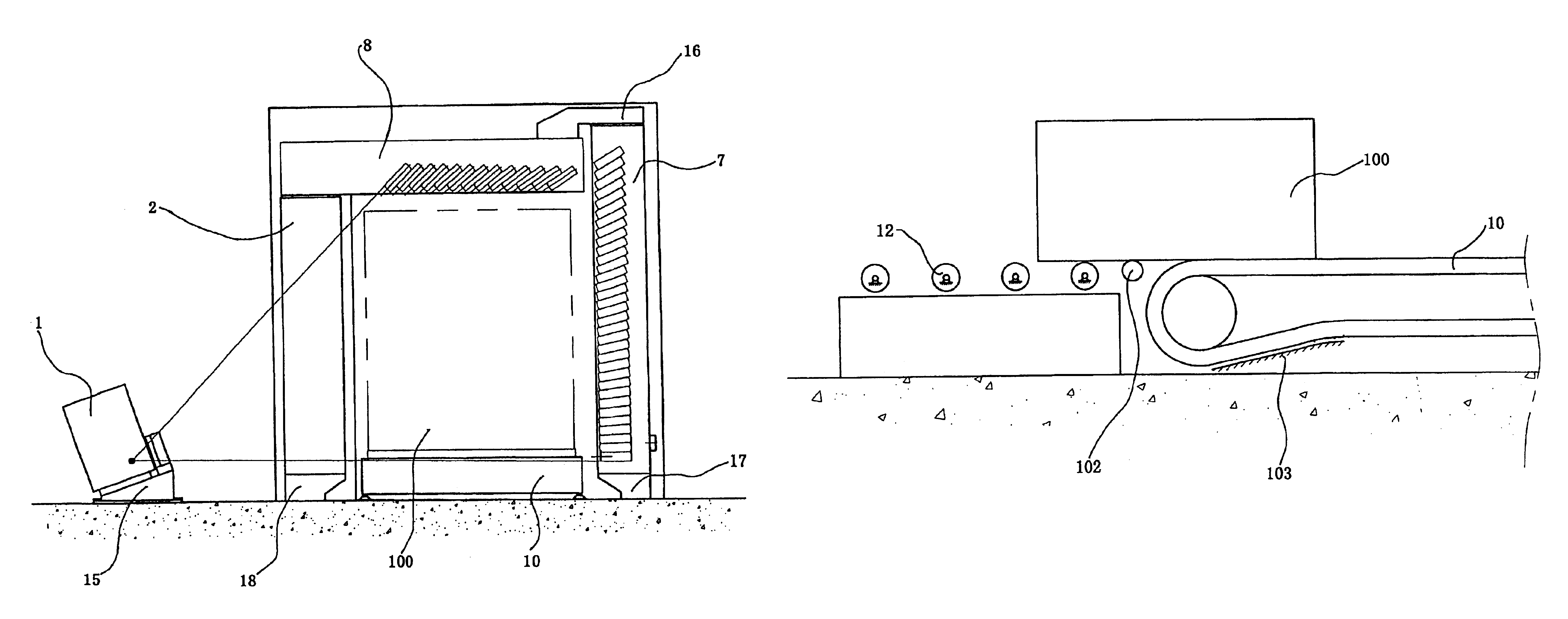
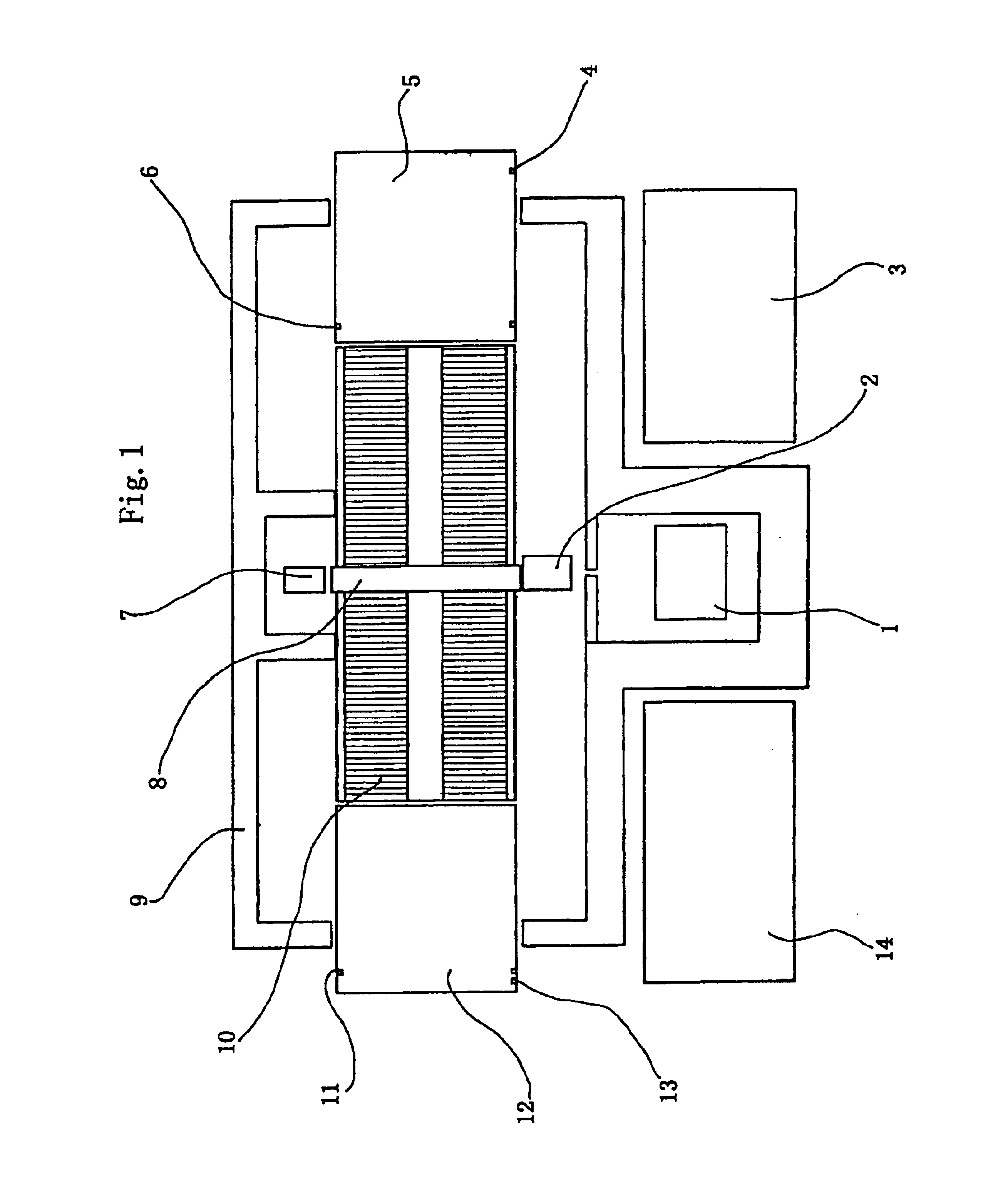
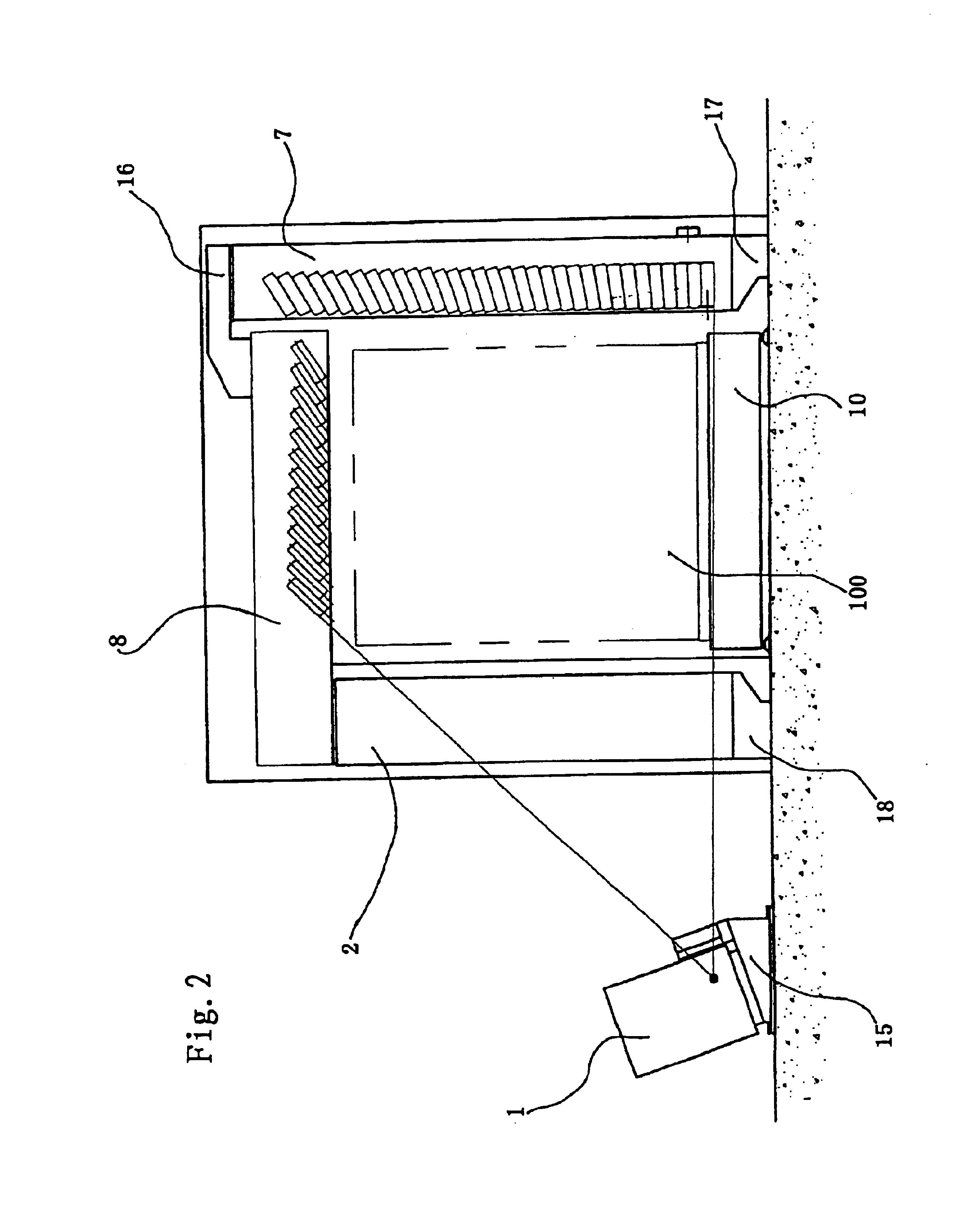
[0030]As shown in FIGS. 1 and 2, an inspection system for air cargoes or vehicles with an accelerator as its radiation source mainly comprises an electronic linear accelerator 1, a collimator 2, a horizontal detector arm 8, a vertical detector arm 7, a conveying device comprising a chain-plank conveyor 10 and roller conveyors 5, 12, radiation shielding walls 9, an instrument cabin 14, and a workroom 3. The accelerator 1, the collimator 2 and the vertical detector arm 7 are respectively provided on the accelerator base 15, the collimator base 18 and the vertical detector arm base 17. The collimator 2 is provided between the conveying device and the accelerator 1. The horizontal detector arm 8 is supported by the upper end of the collimator 2. The vertical detector arm 7 is located in the side opposite to the accelerator 1. The horizontal detector arm 8 is provided over the conveying device. One end of the horizontal detector arm 8 is connected to the vertical detector arm 7 via the connecting body 16, while the other end of the horizontal detector arm 8 is supported by the collimator 2. A stable portal-shaped frame is formed by means of the collimator 2, the horizontal detector arm 8 and the vertical detector arm 7. Under the portal-shaped frame, the air cargoes are carried by the conveying device comprising roller conveyors 5, 12 and a chain-plank conveyor 10 to pass through the scanning tunnel. The scanning operation is controlled in the workroom 3 which is provided with a console. Radiation shielding walls 9 with lap joints are provided on both sides of the scanning tunnel. The radiation shielding wall 9 is a kind of steel frame with a lead plate sandwiched between the inner wall and the outer wall. In operation, after the power supply is ready, turn on the breaker of the electric cabinet for every subsystems, then use the key to turn on the power supply switch located on the control panel of the electric control cabinet to supply electric power for the electric control cabinet, so that the inspection system is started. On the panel, there are provided with function keys to enter such subsystems as the scanning control subsystem, the image data acquisition subsystem, the accelerator subsystem, the scanning unit subsystem, etc. Pressing down different function keys, the inspection system accesses different subsystems. When pressing down the function key for the scanning control subsystem, an indicator light is bright to show the scanning unit is ready for work, and the interface of the scanning control subsystem appears on the screen, so the operator can check whether everything is in its normal state. After making sure that nobody is left in the radiation area, the cargo's owner can press down the “loading” button 4 on the panel, so the loading rollers begin rotate in the forward direction. Once the container 100 reaches to the photoelectric switch 6, the loading is end, and the loading rollers stop. Therefore, the container stop moving forward, and the “end loading” indicator light on the panel becomes bright. As a result, the container is ready to be inspected. Then, the loading rollers and the chain-plank conveyor are both started so as to carry the container to move forward. When the container reaches to the scanning cross section, if every subsystems are ready to work, the safety interlock switch on the panel is on, so the accelerator 1 emits a conical X-ray beam which is transformed into a fan-shaped X-ray beam after passing through the collimator 2. In this time, the loading rollers stop, and the X-ray beam passing through the collimator 2 becomes the fan-shaped X-ray beam which is perpendicular to the floor. The tips of the detectors provided within the horizontal detector arm 8 and the vertical detector arm 7 are in the same plane as the fan-shaped X-ray beam. The X-ray beam radiated from the accelerator 1 penetrates the container being inspected, so as to be received by the detectors provided within the horizontal detector arm 8 and the vertical detector arm 7, then the X-ray beam received by the detectors is transformed into electrical signals which are input into the image data acquisition module provided in the instrument cabin 14 located outside of the scanning tunnel, then the image signals are transferred to the operation & inspection module by the image data acquisition module, then the image signals are transferred by the operation & inspection module to the computer in the workroom 3. As a result, the radiographic image of goods contained in the container is displayed on a computer screen on the panel of the workroom 3.
[0031]Whenever the container 100 leaves the scanning cross section, the accelerator stops emitting the X-ray beam. When the container reaches to the position of unloading photoelectric switch 11, the unloading rollers and the chain-plank conveyor stop. The container is ready for unloading, and the “ready for unloading” indicator light on the panel becomes bright. Then the unloading rollers rotate so as to automatically unload the container. After the container is fully unloaded, the unloading rollers stop. Normally the container will not stop moving during being scanned. In emergency, however, press down the “stop” button on the console to stop the scanning unit and turn off the power supply.
[0032]In addition, the technical solution according to the present invention can be used not only for the air cargoes, but also for their medium or small type carrying vehicle.
[0033]According to the present invention, the stable portal-shaped frame enclosed by the collimator, the horizontal detector arm and the vertical detector arm can also be used in the line of the container conveying rollers of the current airports to perform the inspection work.
[0034]Preferably, as shown in FIG. 3, the conveying device according to the present invention is composed of a roller conveyor 12 and a chain-plank conveyor 10, and an idle transition roller 102 is provided between the roller conveyor and the chain-plank conveyor. In order to prevent the return chains of the chain-plank conveyor 10 from hanging down, a supporting plate 103 is employed.
[0035]During inspection, the air cargoes 100 are carried by the rollers to be smoothly conveyed to the chain-plank conveyor which is stably circulated to carry the air cargoes to pass through the scanning cross-section. As the chain-plank conveyor run stably, a stable scanning image can be obtained.
[0036]As shown in FIG. 4, in the case of the inspection system according to the present invention is used for inspection of a vehicle, the chain-plank conveyor 10 of the conveying device is arranged in the air cargo conveying line. At the both ends of the chain-plank conveyor 10, there is provided with a transition means which facilitates the vehicle 101 to go up to the chain-plank conveyor from the air cargo conveying line or go down to the air cargo conveying line from the chain-plank conveyor. Said chain-plank conveyor 10 is set up on the floor, and said transition means is a wedge 110, which has an inclined surface to smoothly bridging the floor with the chain-plank conveyor.
[0037]Thus, by simply putting the chain-plank conveyor 10 on the floor and employing the wedges 110, the vehicle 101 can easily go up to the chain-plank conveyor from the air cargo conveying line or go down to the air cargo conveying line from the chain-plank conveyor. In this way, no cost for construction of the pit occurs, and no cost for construction of water draining system occurs. In addition, the cost for daily maintenance is also lowered. The construction cost of the inspection system according to the present invention is minimized.
[0038]Moreover, if possible, the chain-plank conveyor can be provided in a pit, so that the upper surface of the chain-plank conveyor can be kept in the same level as the floor and the transition means is simplified as a bridging plate. In this case, the vehicle is easier to access to the chain-plank conveyor.

PUM

no PUM

Description & Claims & Application Information

We can also present the details of the Description, Claims and Application information to help users get a comprehensive understanding of the technical details of the patent, such as background art, summary of invention, brief description of drawings, description of embodiments, and other original content. On the other hand, users can also determine the specific scope of protection of the technology through the list of claims; as well as understand the changes in the life cycle of the technology with the presentation of the patent timeline. Login to view more.

Similar technology patents

Image reading apparatus

InactiveUS20050238205A1improve efficiency
Owner:FUJIFILM BUSINESS INNOVATION CORP

Method and device for updating data in distributed storage system

ActiveCN103294675AImprove efficiencySolve data consistency
Owner:SHANDA INTERACTIVE ENTERTAINMENT

Classification and recommendation of technical efficacy words

  • improve efficiency
Why Eureka
Try Eureka