Method for manufacturing air compressor assembly

Inactive Publication Date: 2005-08-02
BLACK & DECKER INC
View PDF12 Cites 15 Cited by
  • Summary
  • Abstract
  • Description
  • Claims
  • Application Information

AI Technical Summary

Benefits of technology

[0007]Accordingly, the present invention is directed to a method for manufacturing an air compressor assembly. In one aspect of the present invention, the method includes a step of submerging a welded air tank into a dip tank that contains cooling liquid treated with a corrosion inhibitor between

Problems solved by technology

Manufacturing an air compressor assembly is a time consuming and expensive process.
However, after welding, the air tank is typically too hot to allow assemblers to begin final assembly.
This may greatly decrea

Method used


Image

  • Method for manufacturing air compressor assembly
  • Method for manufacturing air compressor assembly
  • Method for manufacturing air compressor assembly

Examples


Example

[0030]Reference will now be made in detail to the presently preferred embodiments of the invention, examples of which are illustrated in the accompanying drawings.

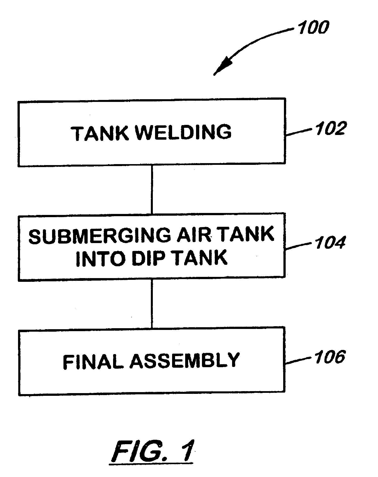
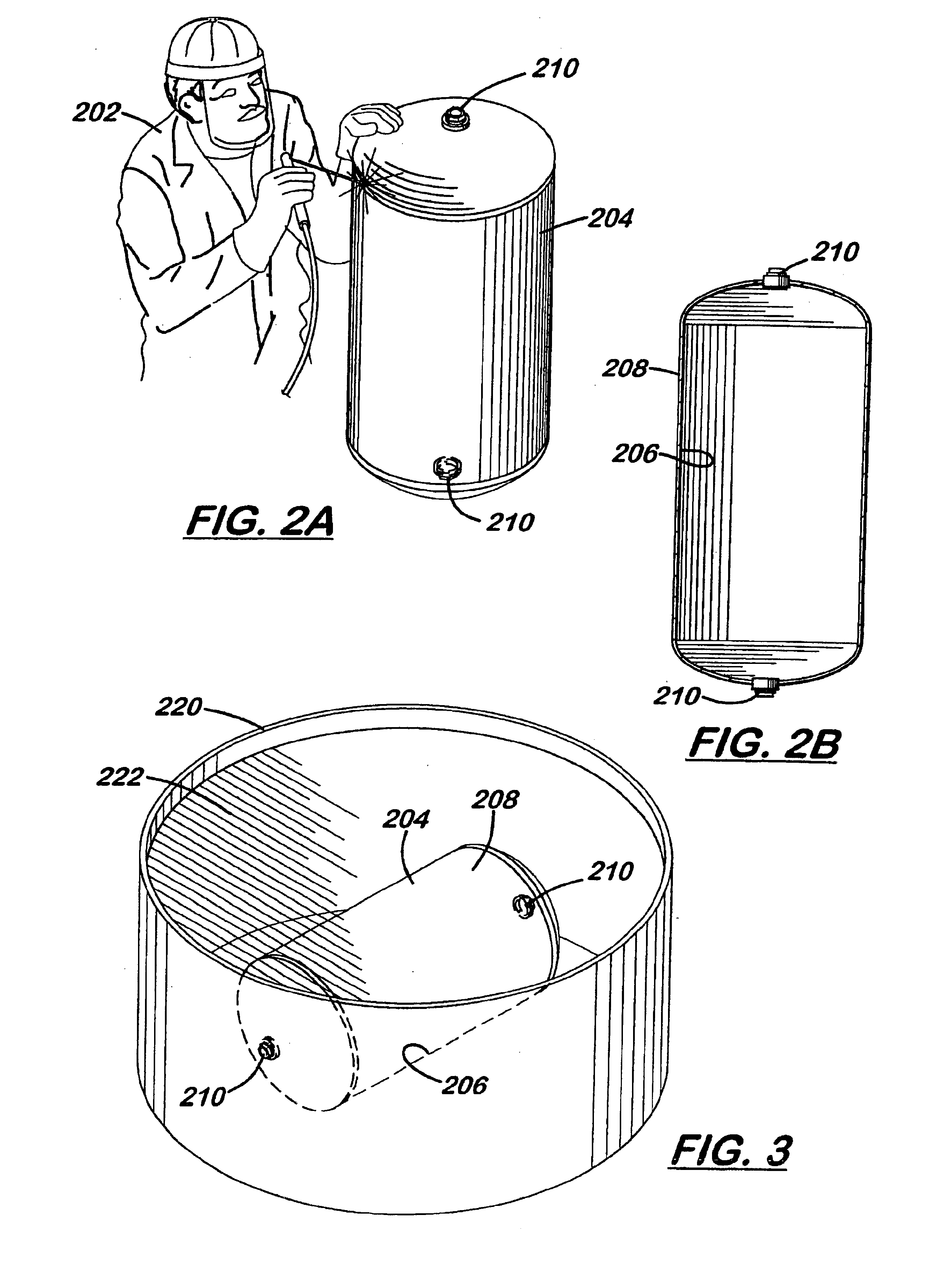
[0031]Referring to FIG. 1, a flow chart illustrating an exemplary method 100 for manufacturing an air compressor assembly in accordance with the present invention is shown. The method 100 starts with step 102, in which an air tank is welded. Typically, after welding the air tank is too hot to allow assembly handlers to begin final assembly. Additionally, the welding process may reduce the corrosion resistance of the tank metal (e.g., steel) in the heat-affected zones of the tank. To solve these problems, in step 104 the welded air tank is submerged into a dip tank which contains cooling liquid (e.g., water) treated with a corrosion inhibitor. In a preferred embodiment, the welded air tank is submerged into the dip tank with all air access ports open to allow cooling liquid to coat both the inside and outside surfaces to ma...


PUM


Abstract

A method for manufacturing an air compressor assembly including, between a tank welding step and a final assembling step, a step of submerging a welded tank into a dip tank that contains cooling liquid treated with a corrosion inhibitor. In a preferred embodiment, in the submerging step, all air access ports of the welded tank are open to allow the cooling liquid to coat both the inside and outside surfaces of the air tank to maximize corrosion inhibitor protection and increase tank cooling rate. The method for manufacturing an air compressor assembly according to the present invention may be used in manufacturing air compressor assemblies in various styles.

Description

CROSS-REFERENCE TO RELATED DOCUMENTS[0001]The present application claims the benefit under 35 U.S.C. § 119(e) of U.S. Provisional Application Ser. No. 60 / 408,860, filed Sep. 6, 2002. Said U.S. Provisional Application Ser. No. 60 / 408,860 is herein incorporated by reference in its entirety.[0002]The present application herein incorporates the following United States Patent Applications by reference in their entirety:[0003]“Express Mail”Attorney Docket NumberMailing Label No.Filing DatePTG 02-96-2EV 338 284 628 USJun. 20, 2003PTG 02-96-3EV 338 284 614 USJun. 20, 2003FIELD OF THE INVENTION[0004]The present invention relates generally to the field of air compressors, and particularly to a method for manufacturing an air compressor assembly.BACKGROUND OF THE INVENTION[0005]Manufacturing an air compressor assembly is a time consuming and expensive process. It conventionally requires the use of several manufacturing cells. For example, air compressors and motors may be built and assembled i...

Claims


Application Information

Patent Timeline
IPC IPC(8): F04B41/02F04B41/00F04B39/16
CPCF04B41/02
Inventor BURKHOLDER, ROBERT F.CURNEL, SCOTTWOOD, MARK W.WRIGHT, MATTROBENALT, DAVID W.RUSSELL, KURT
Owner BLACK & DECKER INC
Why Eureka
Try Eureka