However, this method was not free from the problems of a lack of safety due to the tilt operation and the drop of productivity due to the measurement time.
Though capable of accurately measuring the temperature, these measurement probe systems would likely not continuously measure the molten
metal temperature during refining and would likely not either execute fine refining control because they were intermittent
temperature measurement systems.
Because the measurement probe for the temperature measurement was consumed, the cost was high, too.
It is not possible at present to judge from the output of the
radiation thermometer whether the field is closed or the temperature has actually dropped.
Therefore, this method involves the problem of reliability of the measurement value.
All these problems result from the fact that the measurement is so-called “point measurement” because the
optical fiber is used.
However, using method, the cost becomes high due to the consumption of the
optical fiber.
In the apparatuses using the image fiber described above, however, the fiber should be fitted and removed at the time of the exchange of the converter, the AOD furnace, etc., even when conformity of the optical axes is once secured, and the optical axes are likely to greatly deviate at this time.
The image fiber, that is particularly expensive, is likely to undergo
thermal damage due to excessive, heat and is sometimes broken when it is fitted and removed.
However, according to the construction of this centering portion, each part constituted by the concave and convex portions employs fitting and
close contact and cannot easily adjust the deviation of the
optical axis.
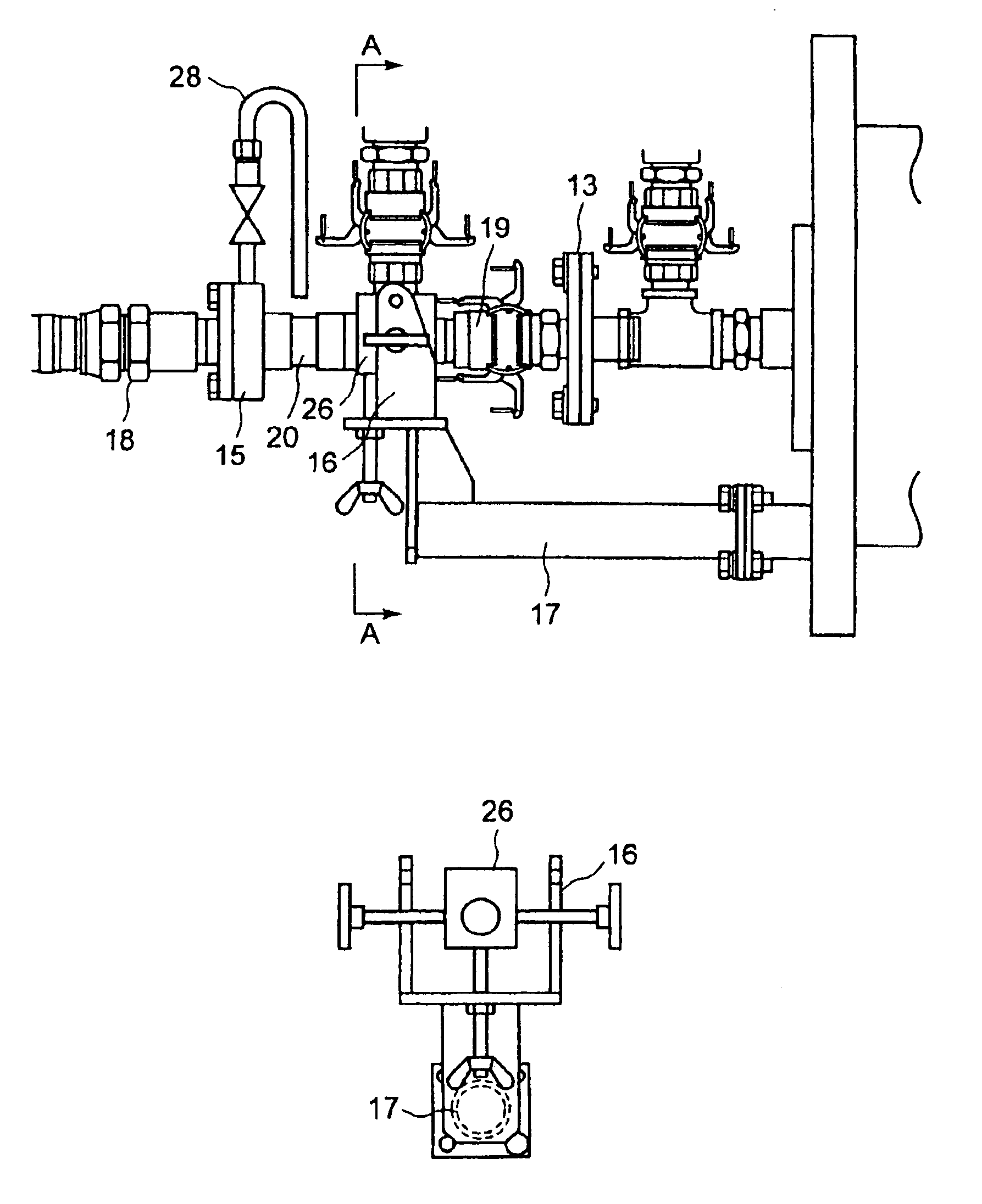
Because
coupling with the nozzle uses a
flange structure, fitting / removal needs a long time and a quick operation in the high temperature
atmosphere cannot be carried out easily.
Because two nozzle gas introduction portions are generally necessary in the case of a double
pipe nozzle in comparison with the single
pipe nozzle in this
system, the distance between the distal end of the image fiber and the distal end of the nozzle as a thermal
radiation light inlet becomes great and the adjustment of the optical axes can become difficult.
As a result, the
radiation thermometer measures the solidified metal having a lower temperature than the molten metal and a great error occurs in the measurement value.
It has been found that according to this method, however, the melting loss of the nozzle drastically proceeds due to the rise of the molten metal temperature and the measurement cannot be made.
When the flow rate is insufficient, critical problems develop in that the molten metal enters the nozzle and not only the light
receiver is broken but also the molten metal flows outside.
According to this method, however, the nozzle
diameter is as small as 3 to 5 mm and the thickness of the
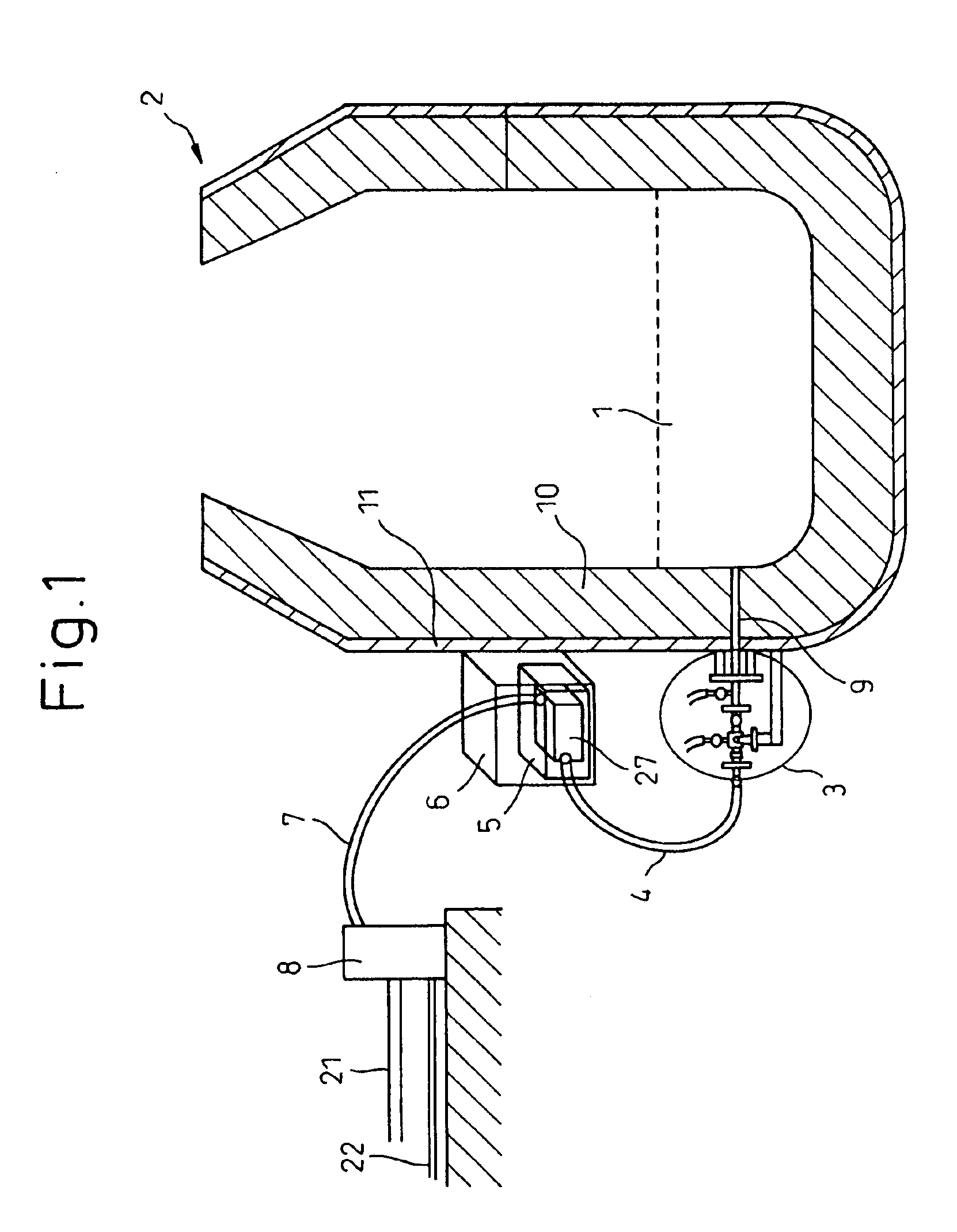
refractory through which the nozzle penetrates is as large as about 1 m. Therefore, when bending occurs in the nozzle due to
thermal deformation of the
refractory, the problem occurs in that the field capable of being observed cannot be secured sufficiently.
The temperature change of the molten metal is great inside the refining furnace due to the unbalance between exothermy resulting from blowing of
oxygen and heat removal resulting from the addition of a cooling material and clogging of the nozzle distal end by the solidified metal cannot be completely prevented.
Such fine adjustment of the light reception portion at the distal end of the image fiber is difficult if not impossible to attain by the prior art technologies and a new counter-measure is needed.
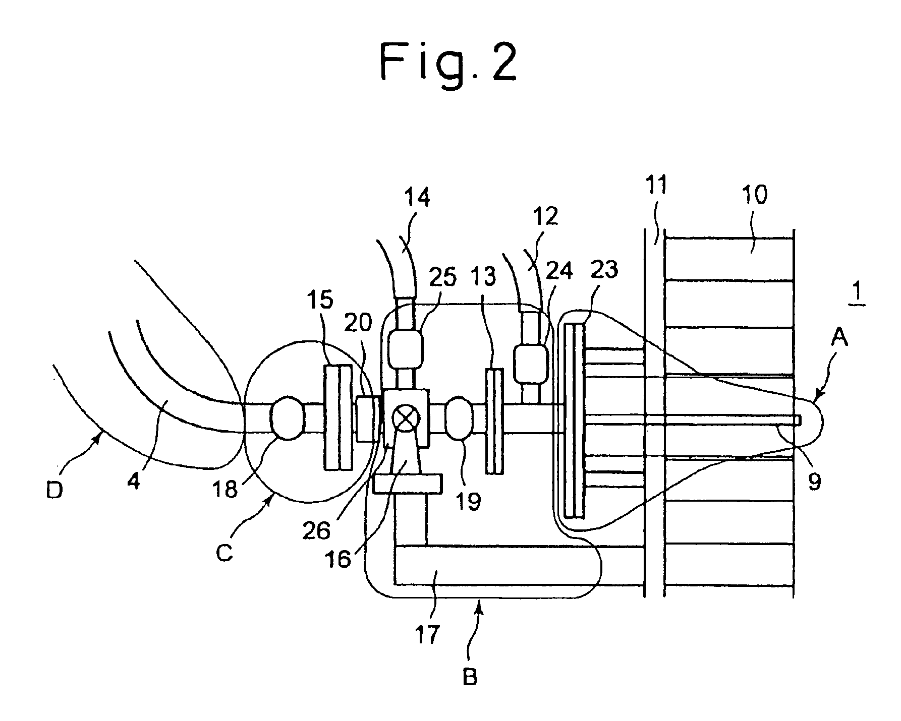
Because the
inert gas is pressure fed into the temperature measurement nozzle to prevent invasion of the molten metal, the field of the image fiber becomes narrow or the nozzle is clogged when the molten metal in the proximity of the distal end of the nozzle is solidified and cuts off thermal radiation light from the molten metal.
However, when this method is excessively executed, the melting loss of the nozzle becomes remarkably great and when the timing of the execution of this method is not proper, the solidified metal cannot be melt and flow away even when the
oxygen gas is blown.
These proposals do not concretely disclose the execution method and the melt-flowing of the
base metal by
oxygen cannot be utilized effectively.
Further, because fine adjustment of the mixing proportion of the gas is difficult, it is difficult to conduct the molten metal temperature measurement with high accuracy.
This method is a so-called “batch temperature measurement method” that measures the temperature at certain points, and cannot accomplish continuous temperature measurement of the molten metal.
As described above, a large number of problems have yet been left unsolved and quick solution of these problems has been urgently required.

